User Manual DEV 5072
10
Copyright DEV Systemtechnik GmbH 2016-2017
3.2
Product Drawings
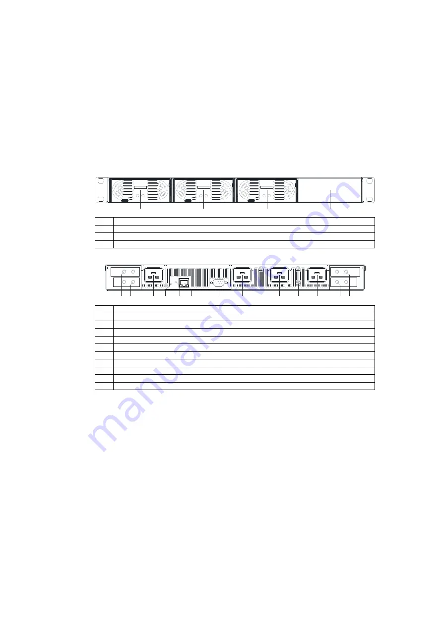
The rear side of the DEV 5072 is identical for all product configurations.
For the appearance of the front side of the DEV 5072, it has mainly to be distin-
guished which type and number of power supply modules is installed.
Thus, only a single drawing of the front side is provided, other configurations can
be easily derived from that.
For a product view in combination with the DEV 5101 Online UPS for DEV 5072,
please refer to the DEV 5101 user manual.
Front View:
D C
A C
H F E 2 5 0 0 -4 8 /S
D C
A C
H F E 2 5 0 0 -4 8 /S
D C
A C
H F E 2 5 0 0 -4 8 /S
P S
2
P S
1
P S
3
P S
4
PS
1
Slot for power supply module 1 equipped with a 48 V power supply module
PS
2
Slot for power supply module 2 equipped with a 48 V power supply module
PS
3
Slot for power supply module 3 equipped with a 48 V power supply module
PS
4
Slot for power supply module 4 covered with a blind plate
Rear View:
R e s e t
S ta tu s
A C
3
A C
2
A C
1
A C
4
G N D
-
A
+
A
C o m
E th
-
B
+
B
S ta tu s
R e s e t
+B, -B Secondary DC output terminals
AC
4
AC plug for power supply module slot 4
Reset "Reset" push button
Status "Status" LED
Eth Ethernet connector, RJ-45
Com Serial interface connector, Sub-D 9 (f)
AC
3
AC plug for power supply module slot 3
AC
2
AC plug for power supply module slot 2
GND Grounding bolt
AC
1
AC plug for power supply module slot 1
-A, +A Primary DC output terminals


