background image

User Manual DEV 7xxx Optribution® Modules 

 Copyright DEV Systemtechnik GmbH 2012-2017 


2.2


Limitation of Warranty  

The preceding warranty does not apply to defects resulting from:  


improper site preparation or site maintenance;  


improper or inadequate interfacing of the product;  


unauthorized modification or misuse of the product;  


the application of software supplied by the customer;  


improper or inadequate maintenance of the product;  


operation beyond the environmental conditions specified for the product. 


2.3


Warnings  

The following safety measures must be observed during all phases of operation, 
service, and repair of the equipment. Failure to comply with the safety precautions 
or warnings in this document violates safety standards of design, manufacturing, 
and intended use of the equipment and may affect the built-in protections. 
DEV Systemtechnik shall not be liable for the failure of users to comply with these 
requirements. 
Disconnect the chassis in which the optical modules are applied from any external 
power line before opening of the housing. In any case, the equipment is to be 
opened by trained service staff, only. 

Environmental Conditions  
This equipment is designed for indoor use and for an ambient temperature range. 


Laser Safety  


Safety of Laser Products  
DEV Systemtechnik recommends to follow the governing standard of the 
country where the product is operated, to assure regulatory compliance, and to 
provide the necessary safety programs to protect the operators and other 
persons who get in contact with the product.  


It is recommended to power down the chassis in which the optical modules are 
applied while working on the optical fiber wiring.  


The optical modules operate with light at a non-visible wavelength. Highest 
caution has to be taken, especially with EDFA optical amplifier modules and 
with optical transmitter modules, since they produce laser light that is capable 
to harm the human eye!  
All optical connectors have to be equipped with the appropriate protection 
cover if no optical fiber is (to be) connected to an optical module.  


Direct exposure to the beam is to be avoided, i.e. do not look into 
unterminated optical ports or at fibers that connect to unknown sources.  

Summary of Contents for 7231

Page 1: ...er Modules DEV 7415 DEV 7425 EDFA Optical Amplifier Modules DEV 7512 DEV 7514 DEV 7518 Optical Splitter Modules DEV 7612 DEV 7614 DEV 7618 DEV 7658 Optical De Multiplexer Modules Optribution Modules DEV Systemtechnik GmbH Grüner Weg 4A 61169 Friedberg GERMANY Tel 49 6031 6975 100 Fax 49 6031 6975 114 support dev systemtechnik com www dev systemtechnik com Revision 2017 11 02 DEV 91 0097 L ...

Page 2: ...plitter Modules DEV 751x 10 3 1 5 Optical De Multiplexer Modules DEV 76xx 11 3 2 Redundancy Principles 12 3 2 1 1 1 Redundancy Options 12 3 2 1 1 No Single Point of Failure NSPoF Options 14 3 2 2 N 1 Redundancy Options 15 4 Installation Instructions 18 4 1 Scope of Delivery 18 4 2 Installation of the Product 18 4 3 Device Factory Settings 18 4 3 1 Factory Settings for the Optical Modules 18 5 Oper...

Page 3: ... is continually changing this division is supposed to improve the documentation update process In addition to the description of the optical modules this Optribution modules user manual explains the general redundancy principles DEV Systemtechnik GmbH declares that this equipment meets all relevant standards and rules Each unit carries a CE mark Please read all instructions before installation or ...

Page 4: ...m any external power line before opening of the housing In any case the equipment is to be opened by trained service staff only Environmental Conditions This equipment is designed for indoor use and for an ambient temperature range Laser Safety Safety of Laser Products DEV Systemtechnik recommends to follow the governing standard of the country where the product is operated to assure regulatory co...

Page 5: ... Transmitter 10 47 1006 MHz SC APC 1550 nm 3 1 1 e DEV 7241 Basic Twin Optribution Transmitter 950 2150 MHz SC APC 3 1 1 f DEV 7244 Optribution Transmitter 10 MHz 700 2300 MHz SC APC Single Input 3 1 1 g DEV 7251 DWDM Optribution Transmitter 700 2300 MHz SC APC with adjustable Gain and Automatic OMI Optimization 3 1 2 a DEV 7331 Basic Optribution Receiver 950 2150 MHz SC APC 3 1 2 b DEV 7332 Advan...

Page 6: ... w d ire c tly w o p tic a l in s tru m e n ts C la s s 1 M L a s e r p ro d u c t 6 1 4 2 3 5 CH 63 DEV 7244 O ptribution Transm itter 10 M Hz 700 2300 M Hz 1 O ptical Output 2a RF LED L Band 2b RF LED 10 M Hz 3 Bias LED 4 O ptical M onitor LED O pt Bias RF RF L Band 10 M Hz Tx O ut L a s e r ra d ia tio n d o n o t v ie w d ire c tly w o p tic a l in s tru m e n ts C la s s 1 M L a s e r p ro d ...

Page 7: ...gh current or the upper limit of the current monitoring interval too much current is drawn is exceeded the LED is red The current monitoring status is indicated in parallel via Web Interface and via SNMP given that the Optribution chassis provides these features Note For the Optribution chassis providing a Web Interface the Bias push button at the modules DEV 7232 DEV 7233 and DEV 7251 can be oper...

Page 8: ... ptical Input 2 O ptical M onitor LED 3 RF LED 1 1 1A 1B O ptical Input A B 2A 2B O ptical M onitor LED A B 3A 3B RF LED A B DEV 7341 Basic Twin O ptribution Receiver O pt In B L Band Rx RF O pt In A RF M on RF O pt CATV Band Rx In 1A 2A 1B 2B 3A 3A 2 3 4 5 1 O ptical Input 2 O ptical M onitor LED 3 RF LED 4 G ain Up Button 5 G ain Down Button 6 M onitor Port DEV 7338 Advanced UHF VHF O ptribution...

Page 9: ...control feature with a gain up push button 4 and a gain down push button 5 to adjust the RF output level of the module Alternatively or exclusively for the DEV 7344 the gain can be adjusted in Local Mode via Web Interface and in Remote Mode via SNMP given that the applied Optribution chassis provides these features Note For the Optribution chassis providing a Web Interface the gain buttons on the ...

Page 10: ... but can be ordered as FC APC Option 07 or as E2000 HRL Option 08 instead 3 1 4 Optical Splitter Modules DEV 751x 1 2 C C 1 3 4 2 C 1 2 3 5 6 7 8 4 DEV 7512 O ptical Splitter 1 2 1 O ptical Input 2A 2B O ptical Outputs 1 2 DEV 7514 O ptical Splitter 1 4 1 Optical Input 2A 2D O ptical Outputs 1 4 DEV 7518 O ptical Splitter 1 8 1 Optical Input 2A 2H O ptical Outputs 1 8 1 2A 2B 2C 2D 2E 2F 2G 2H 1 2...

Page 11: ...ne DEV 7618 with Option Lambda0 optical signal outputs which are used for the input to the optical receiver modules The scenario is equivalent for DWDM applications using DWDM capable optical transmitter modules in combination with DEV 7658 DWDM de multiplexer module s in the transmitter chassis to transmit a number of optical signals via a single fiber This fiber is feeding DEV 7658 DWDM de multi...

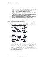
Page 12: ...he inputs of the 2 1 redundancy switch The output of the redundancy switch is the output of the 1 1 redundancy At least the Rx chassis of 1 1 redundancy units requires a CPU module to enable the switching between the main channel and the backup channel With the CPU module equipped the Optribution chassis provides a Web Interface SNMP and the capability to switch autonomously Dual 2 1 Switch M odul...

Page 13: ...el RF Level RF Level RF Level RF Level RF Level RF Level Dual 2 1 Switch M odule Backup Optical Receiver M odule A Backup Optical Transm itter M odule A Dual 1 2 Splitter M odule Backup Optical Receiver M odule B Backup Optical Transm itter M odule B An Optribution chassis with one or more applied 1 1 redundancy options for the receiver side provides by default autonomous switching capability from...

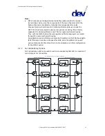
Page 14: ...ped with single link Rx modules and 1 1 Rx redundancy options can be equipped with NSPoF options in addition 1 1 Redundancy Switch M odule Slot 1 Port A Backup Optical Receiver B1 M ain Optical Receiver M 1 O ptical Electrical O ptical Electrical Backup Optical Receiver B2 M ain Optical Receiver M 2 O ptical Electrical O ptical Electrical RF Level RF Level RF Level RF Level NSPoF Redundancy Switch...

Page 15: ... a critical configuration for the NSPoF option 3 2 2 N 1 Redundancy Options N 1 redundancy options are used to realize a redundant optical link to a number of main links per n 1 redundancy O ptical Electrical Electrical O ptical Redundancy Optical Transm itter M odule O ptical Electrical Electrical O ptical O ptical Electrical Electrical O ptical O ptical Electrical Electrical O ptical O ptical El...

Page 16: ...odule on both sides 8 1 12 1 and 16 1 redundancy units are realized with a number of 4 1 redundancy switch modules as well but in combination with one or more multiplexer modules The RF level status and the light condition detection of the optical receiver channels are continuously monitored if Auto Mode is activated on both sides and if the n 1 redundancy is in normal operation There are 2 n 1 he...

Page 17: ...dancy Switch M odule 4 1 Redundancy Redundancy Operation Channel C Transm itter Chassis Receiver Chassis O ptical Fiber O ptical Fiber O ptical Fiber O ptical Fiber O ptical Fiber RF Level RF Level RF Level RF Level RF Level RF Level RF Level RF Level RF Level RF Level If the RF level of the redundancy channel is below the defined RF threshold level or if the light condition of the redundancy chan...

Page 18: ...e N 1 redundancy options are not available for optical modules equipped with two diodes for different frequency ranges DEV 7244 DEV 7344 It is not possible to combine n 1 redundancy options with 1 1 redundancy options 4 Installation Instructions 4 1 Scope of Delivery Please refer to the corresponding Optribution chassis user manual for the scope of delivery 4 2 Installation of the Product For the ...

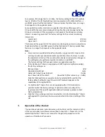
Page 19: ...tments locally at the module alternatively or exclusively changes on the settings may be performed via Web Interface or via SNMP The factory settings for these parameters are application specific If the Optribution chassis is equipped with EDFA optical amplifier module s the factory settings are Manual Gain 0 dB Operation Gain Mode mute Automatic Output Power Setpoint 0 dBm Input Power Limit Thres...

Page 20: ...nteractive services Part 2 Electromagnetic compatibility for equipment German version EN 50083 2 2012 A1 2015 DIN EN 55022 2011 12 Information technology equipment Radio disturbance characteristics Limits and methods of measurement CISPR 22 2008 modified German version EN 55022 2010 DIN EN 55024 2016 05 Information technology equipment Immunity characteristics Limits and methods of measurement CIS...

Page 21: ...ische Verträglichkeit von Geräten Deutsche Fassung EN 50083 2 2012 A1 2015 DIN EN 55022 2011 12 Einrichtungen der Informationstechnik Funkstöreigenschaften Grenzwerte und Messverfahren CISPR 22 2008 modifiziert Deutsche Fassung EN 55022 2010 DIN EN 55024 2016 05 Einrichtungen der Informationstechnik Störfestigkeitseigenschaften Grenzwerte und Prüfverfahren CISPR 24 2010 Cor 2011 A1 2015 Deutsche F...

Page 22: ...User Manual DEV 7xxx Optribution Modules 22 Copyright DEV Systemtechnik GmbH 2012 2017 This Page Intentionally Left Blank ...

Page 23: ... MHz SC APC with adjustable Gain and Slope DEV 7341 Basic Twin Optribution Receiver 950 2150 MHz SC APC DEV 7344 Optribution Receiver 10 MHz 700 2300 MHz SC APC Single Output with adjustable Gain DEV 7415 EDFA Optribution Pre Amplifier Module 1529 1565 nm SC APC DEV 7425 EDFA Optribution Boost Amplifier Module 1529 1565 nm SC APC DEV 7512 1 2 Optribution Splitter 1260 1610 nm SC APC DEV 7514 1 4 O...

Page 24: ...nt of Failure OMI Optical Modulation Index Optribution Optical Transmission and Distribution of RF Signals Optribution is the DEV product line for optical equipment RF Radio Frequency RGC Redundancy path Gain Compensation RU Rack Unit Units of vertical height 1 RU 1 44 45 mm Sometimes simply referred to as U Unit Rx Abbreviation here used for receive or receiver SNMP Simple Network Management Prot...

Reviews: