65 Aleksandar Stamboliyski Str., 8000 Bourgas, Bulgaria
Tel: +359 56 820027, Fax: +359 56 836700
E-mail: office@devabroadcast.com ,Web: www.devabroadcast.com
- 58 -
APPENDIX A
ALARM TRIGGERS
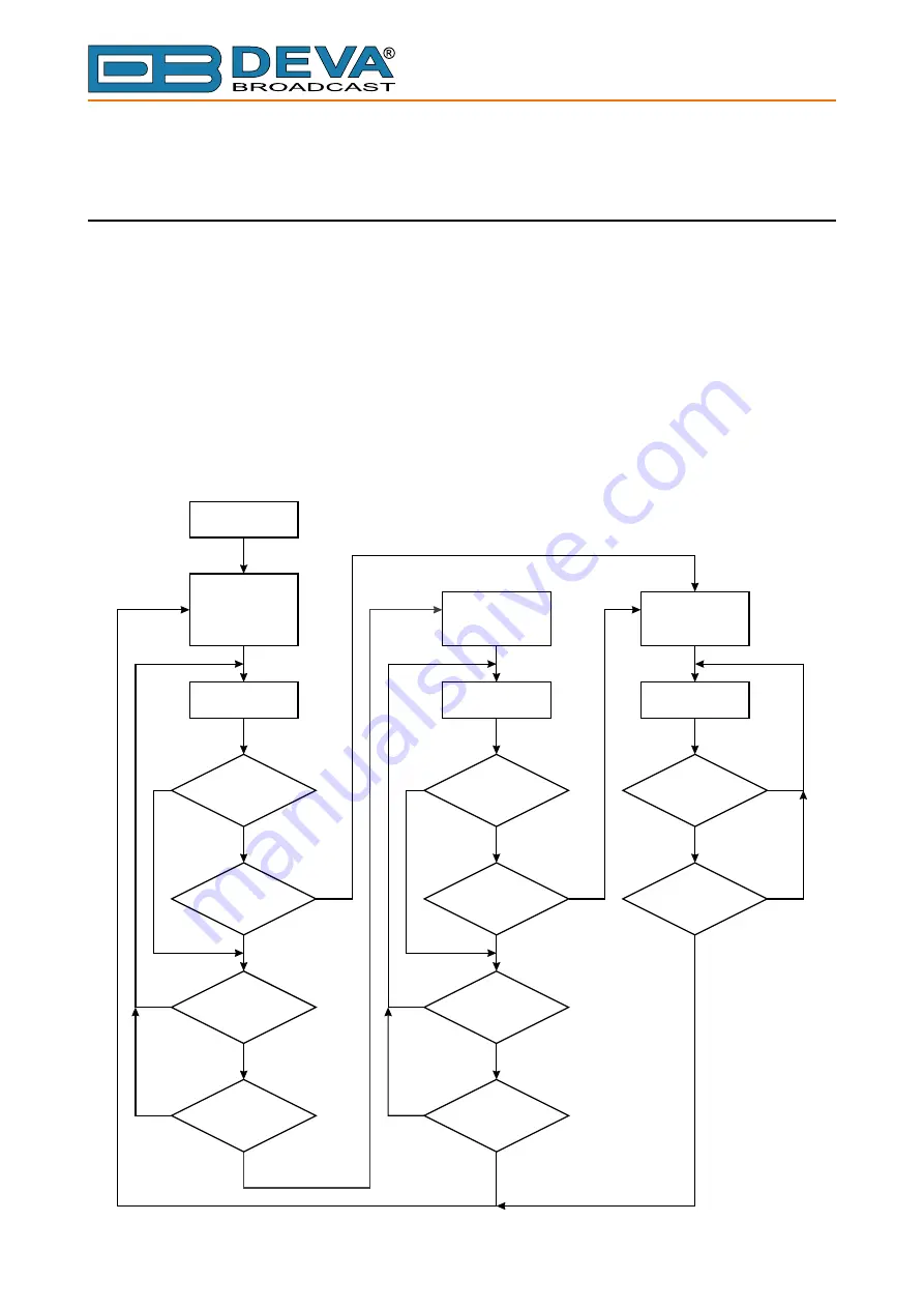
After collecting all the data, the DSP-based core compares the values measured with the
predefined by the user threshold levels, for all the parameters monitored. In case that a parameter
is beyond limits, the device will initiate the sending of an alarm or warning notification via the
selected communication path. All the alarm and warning events are stored in the device’s log. It
is essential that, if there is a very short fault of the signal, with duration shorter than the ‘trigger
time’, the device would not trigger an alarm or warning.
There are several Alarm Triggers for the following parameters: RF, MPX, MPX Power, Left/
Right Audio, RDS Group loss, Pilot and RDS levels. An option for defining different limits for
each of the parameters is present. All these values, the ‘trigger time’ and the ‘release time have to
be assigned separately for each of the alarms.
Start
Idle
(reset alarm
and warning
interval)
Warning Active
(reset
warning interval)
Alarm Active
(reset
alarm interval)
Wait and measure
Wait and measure
Wait and measure
Parameter
out of warning
range?
Parameter
within warning
range?
Parameter
within alarm
range?
Alarm Interval >
Trigger time
Alarm Interval >
Trigger time
Warning Interval >
Trigger time
Warning Interval >
Release time
Alarm Interval >
Release time
Parameter
out of alarm
range?
Parameter
out of alarm
range?
NO
NO
NO
NO
NO
NO
NO
NO
NO
YES
YES
YES
YES
YES
YES
YES
YES
YES
NO
YES
Block Diagram of Alarm Automata


