7
COOLING MEDIUM*
AMBIENT
TEMPERATURE
MULTIPLIER
°
F
°
C
80
27
1.12
90
32
1.06
100
38
1.00
110
43
0.94
INLET COMPRESSED AIR CONDITIONS
INLETINLET TEMPERATURES
PRESSURES
80
°
F
90
°
F
100
°
F
110
°
F
120
°
F
psig
kgf/cm
2
27
°
C
32
°
C
38
°
C
43
°
C
49
°
C
50
3.5
1.35
1.05
0.84
0.69
0.56
80
5.6
1.50
1.17
0.95
0.79
0.66
100
7.0
1.55
1.23
1.00
0.82
0.70
125
8.8
1.63
1.31
1.07
0.91
0.74
150
10.5
1.70
1.37
1.13
0.95
0.80
175
12.3
1.75
1.42
1.18
0.99
0.84
200
14.0
1.80
1.47
1.22
1.03
0.89
3.1 Condenser coil—Clean off accumulated dust
and dirt monthly.
3.2 Moisture separator—Replace filter element
when pressure drop across dryer is excessive
or annually.
3.3 Check separator daily to be sure automatic drain
is discharging.
3.4 Blow down separator weekly by pushing test
button on control panel.
3.4 Rebuild drain mechanism annually.
To facilitate service, maintenance kits are available.
3.0 MAINTENANCE
SIZING
Determining dryer capacity at actual operating conditions
To determine the maximum inlet flow capacity of a dryer
at various operating conditions, multiply the rated capacity
from Table 1 by the multipliers shown in Table 2.
Example: How many scfm can an air-cooled model 400
handle when compressed air to be dried is at 200 psig and
100
°
F; ambient air temperature is 80
°
F; and a 40
°
F dew
point temperature is desired?
Answer: 400 x 1.22 x 1.12 x 1.1 = 601 scfm.
TABLE 2
Air capacity correction factors (Multipliers)
MODEL
200
250
300
400
500
750
Rated capacity of
60 Hz
200
250
300
400
500
750
air-cooled models (scfm) 50 Hz
170
210
250
340
420
630
TABLE 1
Rated capacity (scfm) and pressure drop @ 100 psig inlet
pressure, 100
°
F inlet temperature, and 100
°
F ambient
temperature
*Air-cooled models; water-cooled models use 1.15 multiplier if cooling
water is below 35
°
C, 95
°
F.
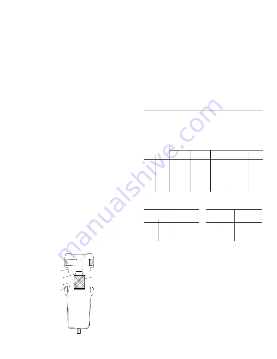
Element o-ring
Separator Element
Bowl o-ring
Threads
Threads
OUTLET DEWPOINT
DEWPOINT
TEMPERATURE
MULTIPLIER
°
F
°
C
38
3
1.0
40
4
1.1
45
7
1.2
50
10
1.3
Dryer Driven Mode- the contacts will be energized
and de-energized in parallel with the refrigeration
compressor of the dryer. Therefore, if the refrigera-
tioncompressor is on, the contacts are energized; if
the refrigeration compressor is off (manually or by a
system fault condition), the contacts will be de-
energized.
NOTE: It is the responsibility of the end-user to properly
design the system control circuitry when using the
auxiliary contact feature.
To select Schedule Driven or Dryer Driven modes:
1.
De-energize unit and disconnect the power
supply to the dryer.
2.
Remove the cabinet panels as necessary to
provide access to the Monitor panel.
3.
On the rear of the circuit board, locate the
jumper pins labeled JA and JB.
4.
Move the jumper to the appropriate setting:
Schedule Driven: jumper position JA
Dryer Driven: jumper postion JB
5.
Wire the auxiliary device into the terminals
1 (Normally Open), 2 (Common) and/or 3
(Normally Closed) on the terminal block TB2.
See wiring diagram for details.
6.
Reinstall the cabinet panels.
7.
Energize the unit.
For Sales & Service Call: 705-722-5747 Ext.1


