background image

3

1

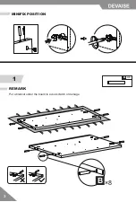
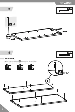
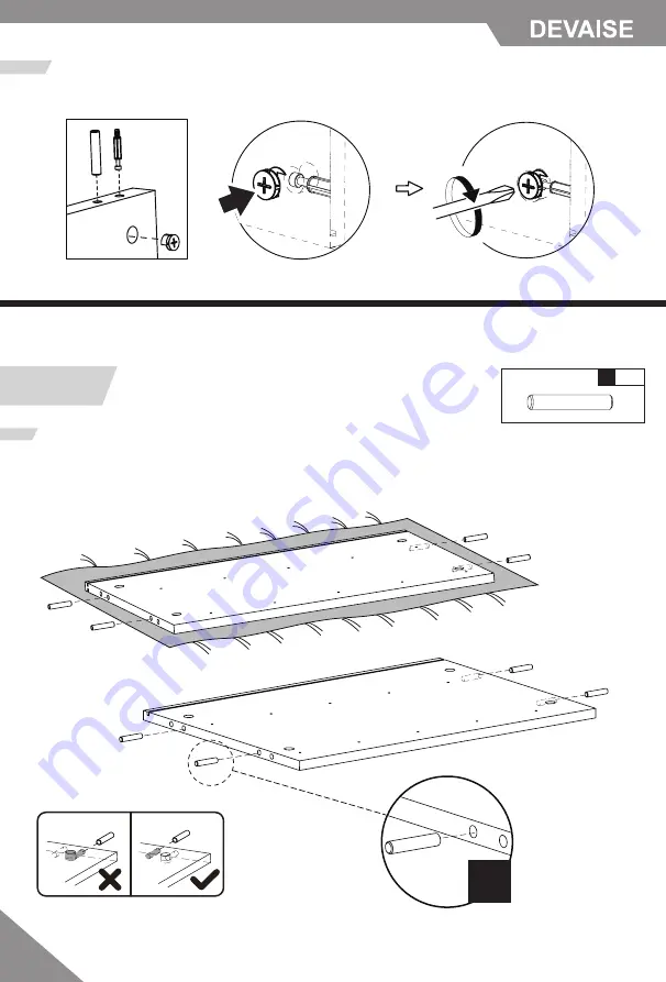
MINIFIX POSITION

X8

B

REMARK

DEV

V

ISE

21

4/

Put a blanket under the board to avoid scratch or damage. 

×8

B

4

3

Summary of Contents for ASNG010

Page 1: ...ASNG010 Wood 5 Drawer Storage Cabinet V3 0 ...

Page 2: ...ructions precisely and only use the product as intended Prior to assembly please check the product for defects or missing accessories If any defects are found or accessories are missing do not use product as damage or injury may occur Please contact us for assistance and replacement It is suggested you regularly check the products bolts and connections to ensure safe use Assemble the item on a sof...

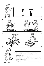
Page 3: ...contact us by email or official website www devaise com We will reply ASAP Enjoy your new purchase Before installation please make sure you have all the hardware the serial numbers are properly labeled corresponging to the list and the quantity is correct ...

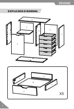
Page 4: ...1 EXPLODED DRAWING X5 2 1 4 3 6 5 5 7 8 9 10 11 12 13 ...

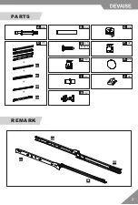
Page 5: ...2 PARTS X32 X32 B X32 C A X5 X2 F D X14 H X8 J CL DL DR CR X76 E X2 G X4 I X2 K REMARK DL DR CR CL M4x14 ...

Page 6: ...3 1 MINIFIX POSITION X8 B REMARK DEV V ISE Put a blanket under the board to avoid scratch or damage 8 B 4 3 ...

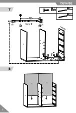
Page 7: ... drawers will not be installed perfectly Please do not install the bottom drawer runner part in this step Otherwise it will not be able to install the connector housing Part C the bottom drawer runner part will be installed in step 7 REMARK X16 E M4x14 X4 CL X4 CR CL CR TOP BOTTOM E E E E E E E E E E E E E E E E 4 3 ...

Page 8: ...5 3 4 2 1 X4 B X12 A REMARK Please do not screw too deep or too shallow A 12 A 6 B 4 ...

Page 9: ...6 5 6 3 2 2 3 3 1 1 4 4 REMARK X6 C Please make the screw holes on part 2 and part 3 are relative when installing REMARK Let the grooves on part 2 3 4 be connected to the groove on part 1 6 C ...

Page 10: ...7 7 8 11 3 15 1 FRONT CR E 5 5 2 2 3 1 1 4 4 X4 E M4x14 X1 CL X1 CR E E E E CL CR ...

Page 11: ...8 9 10 1 1 2 2 2 4 4 4 6 2 1 4 6 6 6 G F F X6 C X2 G X2 F X16 E M4x14 C 6 G 16 E ...

Page 12: ...9 11 12 X10 B X10 A X10 B X10 A A A A A B B B B 5 5 9 11 12 13 ...

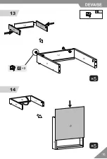
Page 13: ...10 13 14 9 9 9 10 11 11 11 12 12 12 X10 C 5 5 C 2 9 11 ...

Page 14: ...11 15 9 9 9 10 10 11 13 13 13 13 X10 C 5 C 2 ...

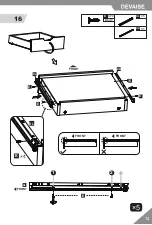
Page 15: ...12 16 DL DR X20 E M4x14 FRONT FRONT FRONT E 1 2 FRONT 3 E E E E 5 X5 DL X5 DR DL E DL ...

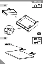
Page 16: ...13 17 18 X4 E M4x14 X2 K K K X10 H 5 2 H 8 E 4 ...

Page 17: ...14 19 X8 E M4x14 2 2 1 1 4 4 6 6 2 4 8 8 E 8 ...

Page 18: ...15 20 21 X4 I 4 I I Please make the groove on board 7 match with the part 7 REMARK ...

Page 19: ...16 22 23 X4 H H 4 ...

Page 20: ...17 24 X8 X8 J E M4x14 8 E J ...

Page 21: ...en the appropriate screws on each case hinge as illustrated Loosen screw Do not loose screw to the end push hinge arm forwards or backwards re tighten screw B B 1 2 DEPTH ADJUSTMENT B B C B Adjust screw to make hinge move left or right to the ideal place C SIDE TO SIDE ADJUSTMENT ...

Reviews: