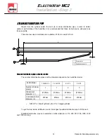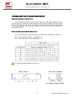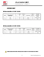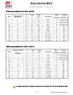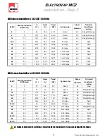
12 Pictures for illustrating purposes only
E
LECTRO
V
AP
MC2
Installation - Step 1
Nota :
Use installation equipment and material appropriate to the surface on which the unit
should be hanged .
The dimensions mentioned underneath are for cabinets without doors.
DETAIL A
R4
R6
10
20
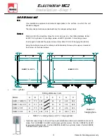
Drilling distances in mm
Model
A B C D E F G
ELMC 1 SM CYL
21 110 425
40 21 425
ELMC 1 LG CYL
41 110 467
40 21 507
ELMC 2 CYL
41 110 760
40 21 800
ELMC 3 CYL
41 110 455 535 40 21 1030
H
385
525
525
525
40
507
1030
467
41
11
0
11
0
41
40
21
41
41
455
535
O
6
2 x
O
6
2 x
A
A
A
A
B
B
C
C
D
G
G
F
E
E
21
F
52
5
H
52
5
H
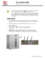
Method:
Mark and drill the mounting holes for 6 mm screws (s.a. the drilling distance table) :
ELMC 1 & 2 cylinders : 4 mounting screws—ELMC 3 cylinders : 5 mounting screws
Insert pegs in holes and the upper screws. Allow about 10 mm for hanging the cabinet.
Hang the cabinet and level it vertically and horizontally. Screw up the upper screws and
then screw up the lower screws.
Detail of
hanging hole
Installation on wall
ELMC 1 & 2 CYL
ELMC 3 CYL
CYL = cylinder
SM CYL = small cylinder, LG CYL = large cylinder
Optionnal support legs to be used for ground installations when a wall installation cannot be
made. Part nb 999989 for ELMC small single cylinder model - Part nb 999992 for ELMC
large single cylinder model - Part nb 999990 for ELMC two cylinder model - Part nb 999988
for ELMC three cylinder model

