21 Pictures for illustrating purposes only
E
LECTRO
V
AP
MC2
Installation - Step 3
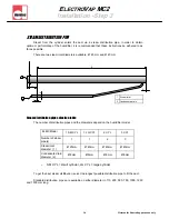
Room ventilation unit
Width Heigth Depth
Weight
Kg
dB
maxi
output
Kg/h
m3/h
Steam connecting
Ø in mm
Compatible with
BP1
260mm 170mm 285mm
2
42-44
5
53
Ø
25
ELMC2
5
BP2
260mm
170mm
285mm
2.6
65-68
30
320
Ø 40
ELMC2 8 to 30
EHFIII
495mm
356mm
406mm
15
48
50
780
Ø 50
ELMC2 40 & 50
1m mini
EHF III
BP 1 & BP2
Dimensions & characteristics
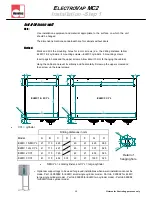
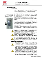
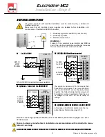
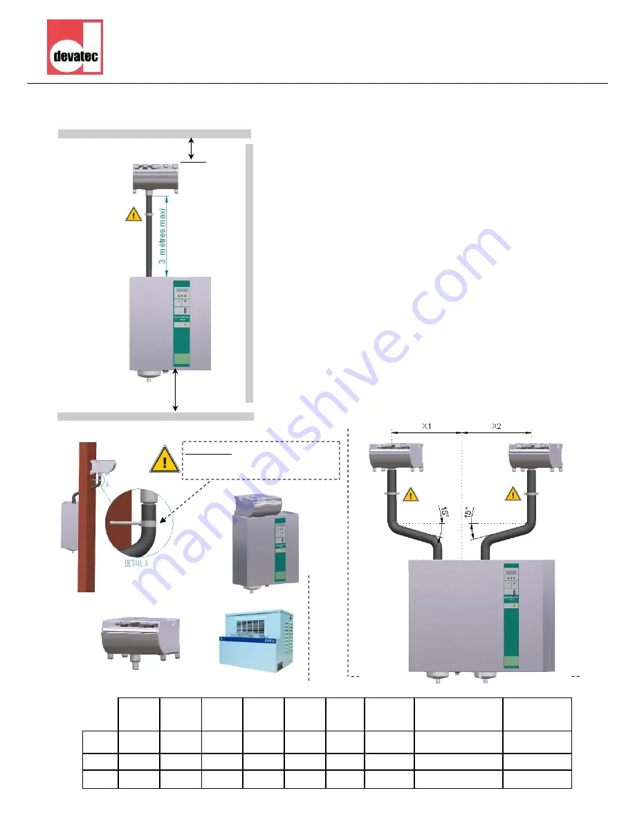
Three ventilation packs permit the use of the humidifier in direct in-space
applications where there is no ductworks :
Blower Pack BP 1 = for capacities up to 5 kg/h
Blower Pack BP 2 = for capacities up to 30 kg/h
EHF II = for capacities up to 50 kg/h
The EHFIII ventilation packs cannot be set on the top of the humidifier (see
after attached pictures). The distance between the humidifier and the ven-
tilation pack(s) should not exceed 3 m.
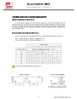
A Ø25mm or Ø40mm direct connection from the humidifier to the blower
pack BP1 or BP2. For use with ELMC 40 to 60, two blower packs BP2
must be installed equally distant (X). (X1=X2). The connection from the
humidifier to the EHF III blower pack is made via a Ø 40/50 mm adaptor.
For use and installation of the Blower Pack ventilation units, please
refer to our Blower Pack technical manual avaliable in English
.
The electrical connection of the ventilation packs to the humidifier is via
terminal block 3 & 4 on the DIN rail.
As far as the EHF-3 is concerned, please revert to the recommenda-
tions given on the EHF-3 information sheet. Never connect the EHF-3
unit on the terminals 3 & 4 of the humidifier when a 100VA transfor-
mer is installed inside the ElectroVap MC2.
Allow a 3 m. distance ahead to the ventilation pack for a free diffusion of
steam.
0,50m mini
Examples of installation
Take care :
Attach hose on wall before
connecting it to Blower Pack.

