34 Pictures for illustrating purposes only
E
LECTRO
V
AP
MC2
Installation - Step 5
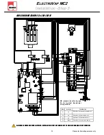
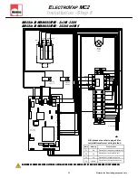
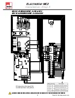
REMOTE INFORMATION BOARD (OPTION)
The wiring of the optional equipment described under must be made with 0.75 mm2 flexible
shielded cable.
ALL WORKS CONCERNED WITH ELECTRICAL INSTALLATION MUST BE CARRIED OUT BY A SKILLED AND QUALIFIED PERSONNEL
.
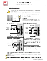
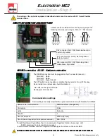
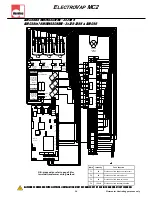
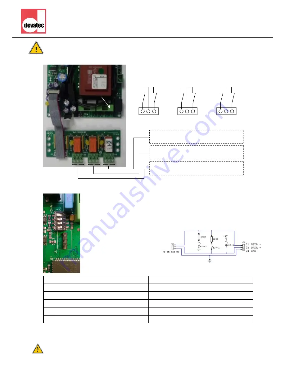
X20 connector (30-31-32): Remote cylinder
maintenance dry contact
X21 connector (33-34-35): Remote general
fault dry contact
X22 connector (36-37-38): Remote steam pro-
duction dry contact.
30 31 32
33 34 35
36 37 38
NO NF
NO NF
NO NF
Contact can be modified in NO or NF by wiring as per the
following schemes (ex: wiring on 30 & 31 = NO contact).
MODBUS connection - RS485 - Hardware connection
The RS485 connection must be plugged on the J1 connector (see pic.) :
Terminal 1 : Data –
Terminal 2 : Data +
Terminal 3 : Signal Ground
The S37 switch is use to enable or disable the line resistor. I most of the case,
those resistor are useless and should be disabled.
See after on the right hand side
the diagram of connection:
Communication settings
Some settings are really important for a great communication with Devatec humidifiers.
To read the status of humidifiers, there is a maximum of registers that can be sent per unit:
- ELMC, maximum 5 can be read in one request.
You must use the smaller number of register if multiple type of units are on the same BUS.
Speed of the communication
9600 Bauds/sec (changeable)
Packet size
8 bits
parity No
parity
Stop bit
1
Timeout response
2500ms (2.5sec)
Time between requests (after response received).
Min. 100ms


