background image

ElectroVap MC 

EG/HG commissioning 

Software assistant

30

Checking and Switching on

.

1

 - After completion of the installation inspection, 

switch on the water supply to the unit.. 

2

 - Switch on the main power supply. 

3

 - The power lamp must be illuminated. 

4

 - Switch on the main power supply I/0 on I. 

The display will default to show the rate of steam 
produced.

The steam bath unit offers 3 main menus: 

USER INFORMATION 

The User Information menu (steam generator  
status) provides information on the operation 
status of the unit. No parameter can be changed 
from within this menu. 

HUMIDIFIER CONDITION 

(Steam Generator Configuration) menu provides 
information only regarding the unit set up. No 
parameters can be changed from within this 
menu.

CHANGING PARAMETER 

The changing parameter System menu 
allows all operating parameters to be 
adjusted. An access code is required to gain 
entry (2 3 4). 

Summary of Contents for ElectroVap ELMC 10 EG

Page 1: ......

Page 2: ......

Page 3: ...trical features Temperature sensor connection Steam bath EG Connecting the optional equipment Steam bath control panel Steam bath HG Connecting the optional equipment ACCESSORIES INSTALLATION Temperature sensor Steam nozzle Perfume dispensor Disinfecting system COMMISSIONING Front panel identification Configuration assistant Changing system parameters menu User information menu Status menu Alerts ...

Page 4: ... air handling systems the information provided should only be used as a guide Please contact your Agent if any doubt CORRECT USE ElectroVap MC steam bathes are ONLY intended for use with air handling systems or direct air humidification ANY OTHER APPLICATION IS NOT CONSIDERED USE FOR THE INTENDED PURPOSE THE MANUFACTURER CANNOT BE MADE LIABLE FOR ANY DAMAGE RESULTING FROM INCORRECT USE WATER Elect...

Page 5: ...test EN 61000 4 6 Immunity to conducted disturbances induced by radio frequency fields EN 61000 4 4 Electrical fast transient burst immunity test EN 61000 4 5 Surge immunity test EN 61000 4 2 Electrostatic discharge immunity test EN 60204 1 Safety of machinery Electrical Equipment of machines Part 1 General requirements EN 292 Parts 1 2 Safety of machinery basic principle mechanical design Manufac...

Page 6: ...in compliance with the European regulations 2002 95 EU RoHS This guideline regulates after July 1st 2006 the use of mercury cadmium lead soldering processes chrome VI as well as PBB and PBDE ELMC steam humidifiers manufactured previously to this date may contain above materials Signature Name MINFRAY Jean Marie Position R D Engineer Date 05 06 2008 6 ...

Page 7: ...ELECTRICAL DIN RAIL ALPHANUMERICAL LCD PANEL POWER LAMP CLEANABLE CYLINDER COMPONENTS OUTLET VALVE INLET VALVE IDENTIFICATION TAG 7 Photos for illustrating purposes only QUARTER TURN DOOR FASTENER ...

Page 8: ... EG HG 22 57 24 01 28 40 38 50 18 30 28 40 40 ELMC 40 EG HG 30 10 31 94 38 45 48 60 28 40 38 52 40 ELMC 40 EG HG 30 10 31 94 43 60 58 70 38 50 48 60 50 ELMC 50 EG HG 37 62 39 88 58 65 68 90 48 60 58 72 60 ELMC 60 EG HG 45 14 47 74 71 102 78 125 58 60 68 102 90 ELMC 90 EG HG 67 65 71 55 ELMC EG Unit remote control cabinet T C sensor ELMC HG Unit with integrate generator T C sensor Determination of ...

Page 9: ...3 to 3 ft from the floor to the bottom of the steam generator 1 25 m 4 ft ahead and 0 60 m 2 ft on the right hand side for allowing easy access for maintenance Mark the mounting holes Drill the holes Insert screws or bolts appropriate for support Screw the screws allowing about 10 mm 3 8 in for hanging the cabinet Hang the cabinet Level the cabinet with a spirit level and tighten up all the screws...

Page 10: ... between 1000 and 350 µ s For the maintenance frequency of the cylinder see the maintenance curve The ELMC incorporates a time counter hours steam KG and shows maintenance messages when appropriate SOFTENED WATER The ElectroVap MC humidifier may be used with softened water 0 TH 2 IMPORTANT Softeners must be programmed correctly Failure to programme the softener correctly may lead to excessive salt...

Page 11: ... 16 Desinfectant nozzle 15 Desinfection pipe 14 7 liters desinfectant tank 13 Desinfecting unit 12 Perfume pipe 11 7 liters perfume tank 10 Perfuseme injection pump 25 Antireturn valve 24 220V electrovalve 23 Perfuse valve 22 Steam bath door to siphon 21 Anti slipping on a slop 20 Floor siphon 19 Extraction of hygienic air 18 Protection glass for 12V bulb 17 Steam bath generator 19 17 8 24 25 15 4...

Page 12: ...12 ElectroVap MC Steam bath EG HG Dimensions ELMC 5 8 10 ELMC 10 230 V single phase 15 20 30 ELMC 40 50 60 ELMC 90 ...

Page 13: ...ain efficiently The Devatec recommended steam hoses should be used for connecting the humidifier to the drain network Regular replacement is recommended If rigid piping is used it must be heat 100 C and pressure resistant PVC material copper galvanized or stainless steel piping prohibited The temperature of the water discharged from the humidifier is between 60 C and 100 C Ensure the pipe work use...

Page 14: ... customer is responsible for ensuring their suitability Please observe local regulations concerning the provision of electrical installations x Check all electrical terminal screws at commissioning after 50 hours operation and at every service thereafter x Take care the ELMC electronic components are very sensitive to electrostatic shocks Appropriate steps must be taken before any operation 14 ...

Page 15: ...32 62 9 66 6 26 21 Large Diam 40 40 40 23 40 76 5 81 31 84 Large Diam 40 40 50 23 50 95 6 101 1 39 75 Large Diam 40 40 60 23 60 114 7 121 2 47 66 Large Diam 40 40 90 23 70 133 8 141 3 55 57 Large Diam 40 40 NB if a circuit breaker must be installed select the appropriate I max value and increase it by a multiplicating factor for safety purposes E G ELMC 10 12A I max 25 coefficient 15 Amperes THE E...

Page 16: ...A lll works concerned with electrical installation must be carried out by a skilled and qualified personnel 14 Wiring the temperature sensor 16 ...

Page 17: ...e ON OFF control of the steam humidifier ELMC EG the ON OFF switch of the steam bath light the setting of the steam bath temperature the display of the temperature within the steam bath the setting of the perfume dispensor The STEAM BATH remote control cabinet can be installed as far as 60 meters from the steam generator The cabinet is watertight and the push bottoms are membrane made For safety p...

Page 18: ...ed wire on terminal n 6 Black wire on terminal n 7 Hole13mm for wall wiring 130 mm Wall mounting Unscrew the 4 screws from the front cabinet of the Steam Bath Remove the front cover Put the rear part of the box on the selected place Mark off the 4 mounting holes the latter are located at the same place at the front screws Remove the back of the cabinet drill with 5mm put the pegs in place position...

Page 19: ...D 12VFOR LIGHITING 220V FOR SCENT Jumper or safety control NON DISPENSOR INSULATED WIRE COMMON 56 55 54 53 52 51 50 49 48 47 46 2 1 DIN RAIL ELMC STEAM BATH IMPORTANT All works concerned with electrical installation must be carried out by a skilled qualified personnel Pictures for illustrating purposes only 19 ...

Page 20: ...ture within the steam bath Variation of the temperature 45 C Steam production indicator Light ON OFF inication in the steam bath Steam production stopped Light is OFF ELMC EG is stopped Using of the panel buttons ENTER STEAM DOWN STEAM UP STEAM ON OFF LIGHT ON OFF Pictures for illustrating purposes 20 ...

Page 21: ...ING 45 C 60 C 45 C 60 C if any of tHe buttons is pressed within 10 seconds the display will show the preveous message again Modification of the perfume set point After the temperature it is possible to set the perfume spreading time with button and button DO NOT FORGET TO CONFIRM THE SETTING 20 50 Example of the scrolling menu Adjustment of the temperature set point if needed Setting of the perfum...

Page 22: ... 23 22 25 24 Brown Green White F3 2A X6 Com X40 F2 2A 4 X9 3 2 X8 1 0 5L3 NC NC 6T3 L3 L2 A2 10 34 L1 8 A1 2T1 NO 4T2 22 K1 14 4 3 1L1 NO 21 13 3L2 5 8 8 3 wire temperature sensor All works concerned with electrical installation must be carried out by a skilled and qualified personnel 22 Connecting the optional equipment Perfume pump Tranformer for 12V lighting 3 x 25W bulbs Desinfecting pump 12 V...

Page 23: ... Position of the temperature sensor Recommended position Vertical position If you install the temperature sensor on the ceiling it may happen that the end of the sensor has some water due to steam condensation If this occurs or in prevention take this end off Never use solvants for cleaning the sensor Part to screw off Supplied equipment Temperature sensor supplied with 10 m long cable 1 sent of 3...

Page 24: ...ozzle union 60mm 30mm 40mm 90mm in standard 120mm out standard upon request Material PTFE food 25mm 40mm Dimensions of the nut 1 1 4Gaz 8mm Build up and example of the installation of the whole steam nozzle Steam nozzle union Steam hoses 25mm or 40mm Nut Steam nozzle Steam Pictures for illustrating purposes o ...

Page 25: ...Wiring the main board and the optional equipment ALL WORKS CONCERNED WITH ELECTRICAL INSTALLATION MUST BE CARRIED OUT BY A SKILLED AND QUALIFIED PERSONNEL 15 25 ...

Page 26: ...tion of the steam hose 25mm 40mm 80mm Wiring diagram 47 46 Equipment supplied Never use solvent to clean the tank and the pump 204mm Material Polyethylen high density food quality TERMINALS ON DIN RAIL OF THE STEAM BATH Ø 40mm Steam inlet Ø 25mm Steam outlet to steam nozzle Parts assembled in factory Pictures for illustrating purposes only Parts assembled in factory ...

Page 27: ...h density Ø 47mm polyethylen food quality Wiring diagram TERMINALS ON THE DIN RAIL OF THE 47 46 STEAM BATH Equipment supplied Parts assembled in factory Tap water Disinfectant nozzle supplied with 50 cm long Ø 4 6 rislan hose and fast union connection Never use solvent to clean the pump and the thank Pictures for illustrating purposes only Parts assembled in factory ...

Page 28: ...eck with menu Changing parameters TIME 30 SEC on page 32 To initiate the disinfection system Press simultaneously on the disinfection time begins to scroll s a the display window PUSH ENTER TO START AGAIN At this moment press the button When the time is over the display reads to go back to the information menu 28 ...

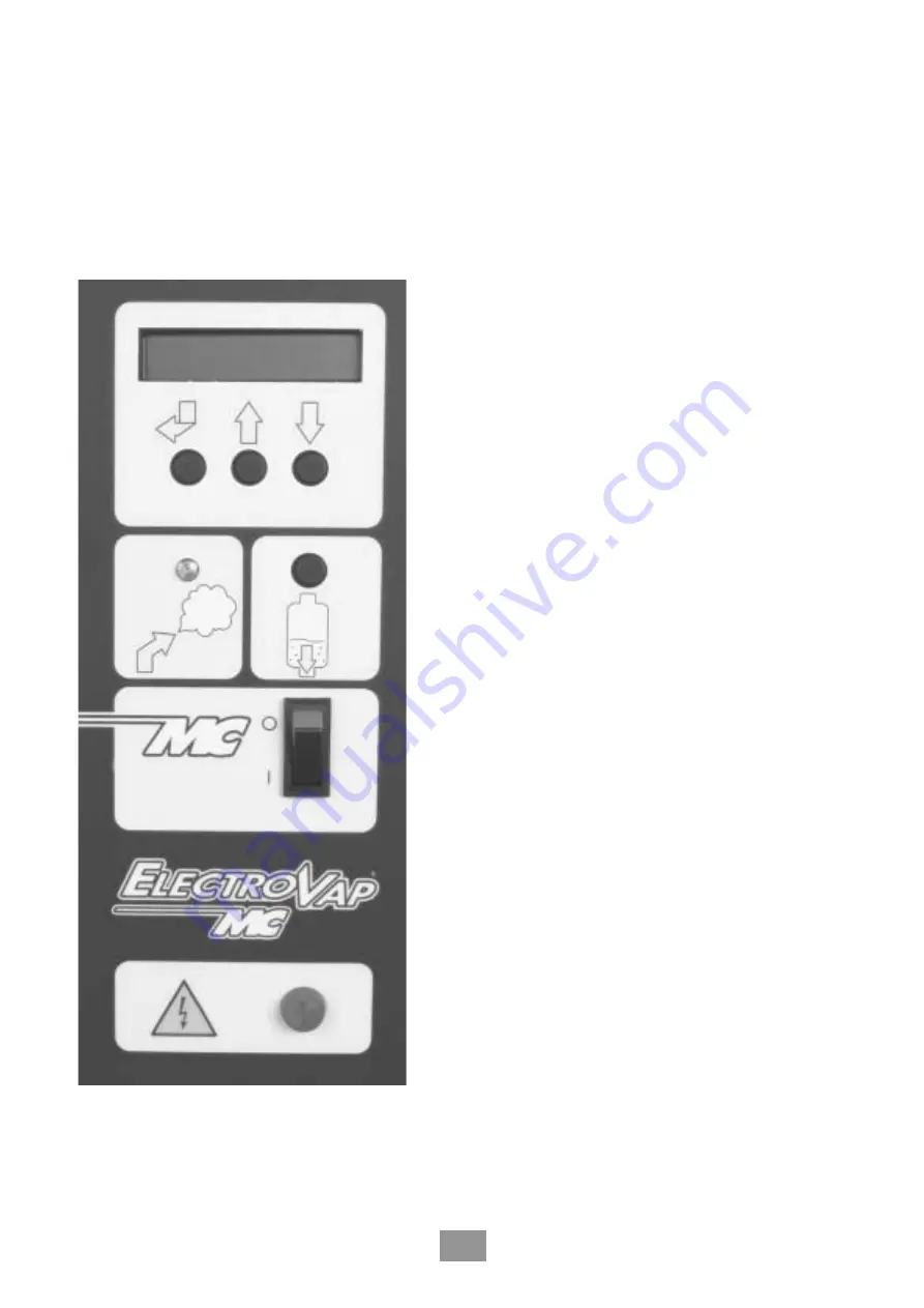
Page 29: ...Vap MC Front panel identification Software assistant Alpha digital display Changing program Scrolling program Scrolling program Manual draining Steam production light ON OFF Switch Power light Identification tag ...

Page 30: ...team produced The steam bath unit offers 3 main menus USER INFORMATION The User Information menu steam generator status provides information on the operation status of the unit No parameter can be changed from within this menu HUMIDIFIER CONDITION Steam Generator Configuration menu provides information only regarding the unit set up No parameters can be changed from within this menu CHANGING PARAM...

Page 31: ...LOW C between steam bath or on off Permits to restrict the steam flow from 20 to 100 in ON OFF and other controls If steam bath HG the display reads Permits to set the perfume injecting frequency in minutes PERFUME INJECTION FREQUENCY MN Permits to set the perfume injecting time in seconds T C STEAM BATH ADJUSTMENT PERFUME INJECTING TIME SEC Permits to set the steam bath temperature Permits to set...

Page 32: ...quency injection If steam bath EG LOCKING THE BUTTON SETTING SB NO INJECTION The screen reads SEC of the disinfection in second If steam bath HG Enables to lock or unlock the buttons of the remote steam bath control panel DRAIN AFTER PERIOD YES NO The unit will be drained if there is no demand for humidity after the selected time Allows the time for the above to be selected Factory setting 72hr op...

Page 33: ...n of the steam bath Indicates the Amps consumption of the unit Steam bath EG ACTUAL CURRENT A The screen reads Steam bath HG T IN THE BATH Indicates the T within the steam bath Indicates the steam demand in the installation from 20 to 100 STEAM DEMAND In the menu change parameter system if the selection option is YES or NO draining if long stop The unit will be drained if there YES The screen read...

Page 34: ...rs during a maintenance interval TIME METER STEAM METER Indicates the number of kg of steam produced during a maintenance interval Indicates the optimum conductivity LOW MINERAL CONCENTRATION ELECTRICAL POWER KW Indicates the power consumed by the steam bath unit in KW Back to first menu 1 2 Reverse timers time before maintenance or production before cleaning When at 0 the display reads maintenanc...

Page 35: ... hours since the first use Indicates the cylinder used Disposable Tap water EV soft water EA DI water ED Cleanable Tap water EV soft water EA DI water ED in the unit TOTAL HOURS RUN WATER USED CYLINDER USED first use Indicates the water used tap water soft water partial DI water DI water supplying the unit POWER SUPPLY V Indicates the voltage selected for the power circuit Indicates the maximum el...

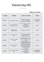
Page 36: ...l off Inlet valve constantly open CHANGE CONTACTOR Check correct water inlet pressure 1 to 6 bar CHANGE INLET VALVE Standard Standard Water supply failure or low P4 ALERT Cylinder is not filling correctly water pressure Drain valve failure CHANGE INLET VALVE Standard CLEAN DRAIN VALVE Blockage at the drain valve Drain valve coil failure P5 ALERT Cylinder not draining correctly CLEAN or CHANGE DRAI...

Page 37: ...y of the cylinder IT IS IMPORTANT TO AVOID DISTORTION THE CYLINDER IN ATTEMPTING TO REMOVE ANY MINERAL DEPOSITS FROM IT Relocate the strainer in the cylinder base Replace the cylinder gasket on the rim of the bottom half of the cylinder and then locate the upper half of the cylinder on the gasket TAKING CARE THAT THE MARKS ARE ALIGNED Refit the nuts and bolts Clean the O ring on the drain valve an...

Page 38: ...that secure the valve body to the drain cup 5 Remove the drain valve body from the drain cup and rinse with clear water ensuring any scale deposits are removed Pay particular attention to the piston seat 6 Assemble in reverse order Drain the steam cylinder fully and remove it from the humidifier Isolate power and water supply before attempting to carry out any maintenance Remove the water inlet ho...

Page 39: ... Notes 39 ...

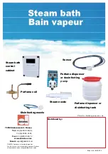
Page 40: ... dispensor or disinfecting tank Steam bath control cabinet Sensor Perfume dispensor or desinfecting Disinfecting nozzle Steam nozzle Photos for illustrating purposes only DEVATEC continues to develop its products For this reason the technical data and specifications of the products can be changed without prior notice Perfume coil Rev 2 4 19 01 11 pump ...

Reviews: