
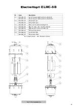


ElectroVap®
ELMC-SB
48
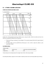
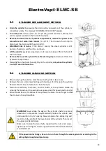
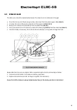
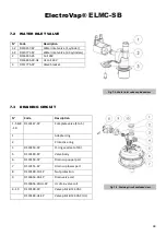
7.2
WATER INLET VALVE
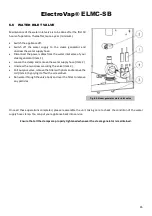
7.3
DRAINING CIRCUIT
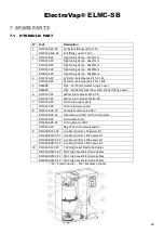
N°
Code
Description
1-2
D110157-SP
Water inlet valve (1 cylinder)
1-2
D110771-SP
Water inlet valve (2-3 cylinders)
2
D116655-24
Coil 24V
D116655-24-UL
UL coil 24V
3
D111775-SP
Valve bracket
N°
Code
Description
1 - 5 & 8
- 10
D110147-SP
Complete valve (1 to 5)
1
Adapter ring
2
Protective ring
3
D110153-SP
O-ring seal (set of 10)
5
D110149-SP
Valve body
6
D110154-SP
Drain cup upper part
7
D110155-SP
Drain cup lower part
8
D110148-10-SP
Nut protection
9
D116656-24-SP
Drain valve coil
D116656-24-UL-SP
UL drain valve coil
4 - 10
D110148-SP
Valve pilot kit 24 VAC
D110148-UL-SP
Valve pilot kit 24 VAC (UL)
Fig. 7-2.
Water inlet valve exploded view
Fig. 7-3.
Draining circuit exploded view
Summary of Contents for ElectroVap ELMC 20-30 SB
Page 1: ...STEAM GENERATOR FOR STEAM ROOM ElectroVap ELMC SB Series Instruction Operation Manual ...
Page 25: ...ElectroVap ELMC SB 25 3 8 6 Wiring diagrams ELMC 5 to 10 Up V 1x200 240V 50 60Hz ...
Page 26: ...ElectroVap ELMC SB 26 ELMC 5 to 30 Up V 3x200 690V 50 60Hz ...
Page 27: ...ElectroVap ELMC SB 27 ELMC 40 to 60 Up V 3x200 690V 50 60Hz ...
Page 28: ...ElectroVap ELMC SB 28 ELMC 90 Up V 3x200 690V 50 60Hz ...
Page 29: ...ElectroVap ELMC SB 29 3 9 OPTION Transformer connection ...
Page 51: ...ElectroVap ELMC SB 51 ...


