background image

ELECTROVAP

®

 RTH-HC 


52 


5.5


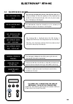
MAINTENANCE ALERTS 


M1: CHECKING 50hr


DUE


This message is displayed 50 hours after the first start-up. 

It 

is then necessary to check the tightness of the electrical and 
hydraulic connections (steam pipe, drain circuit, water supply, 
etc.). The device is not stopped. 

M2: MAINTENANCE


DUE


The  maintenance  timer  has  arrived  at  0,  it  is  necessary  to 
maintain the device. The device is not stopped.


M3: SERVICE OVER


DUE:


DRAINING


M3: SERVICE OVER


DUE:


COOLING


M3: SERVICE OVER


DUE:


STOP UNIT


The  message  M3  is  displayed  when  the  M2  display  is 
displayed and 100 hours have elapsed without maintenance. 


Then the unit is shut down, drained, the tank cooled, and put 
on hold of mandatory maintenance.


MANUAL DRAIN IN


PROCESS


This message is displayed once after pressing the manual 
drain button. The drain is activated.


COOLING CYCLE


IN PROCESS


This means that the manual drain is complete, and you must 
wait for the tank temperature to go down before servicing.


MAINTENANCE


DUE


The tank is empty and cooled, maintenance can be done. 
See technical manual.


TO CARRY OUT A RESET FOR THE ABOVE 

MESSAGES, FOLLOW THIS PROCEDURE:


-Switch the unit to drain by pressing the manual drain button (4). 
-Press button 3 for at least 5 seconds.


4  

Summary of Contents for ElectroVap RTH-HC Series

Page 1: ...ElectroVap HUMIDIFIERS RTH HC Series Instruction Operation Manual ...

Page 2: ...E DRAINING WITH SIPHON 18 3 6 DRAIN HOSE CONNECTION 19 3 7 ELECTRICAL CONNECTIONS 21 3 8 ELECTRICAL WIRING 22 3 9 OPTION TRANSFORMER CONNECTION 42 4 COMMISSIONING 43 5 SYSTEM MANAGEMENT 44 5 1 STATUS MENU READ ONLY 44 5 2 SETUP MENU 46 5 3 CONTROL SYSTEM MENU 47 5 4 CHANGE SETTINGS MENU 49 5 5 MAINTENANCE ALERTS 52 5 6 DEFAULT MESSAGE 53 6 MAINTENANCE 58 6 1 STAINLESS STEEL TANK 58 6 2 DRAIN VALVE...

Page 3: ...ning can lead to serious bodily injury or death to people and or significant material malfunctions Danger High temperature The ElectroVap RTH HC uses steam during the operation and therefore surfaces and pipe work become very hot Ensure that equipment not sustaining high temperatures is kept away Electrostatic hazard The components of the device may be subject to deterioration as they are very sen...

Page 4: ...d or softened water It is absolutely forbidden to inject a chemical into the hydraulic system Make sure that the water supply pressure does not exceed 6 bar Always be careful that the installation meets local standards ELECTRICITY The user ensures that electrical installation will be carried out by an authorized technician in this field The installer must provide the correct cable section as well ...

Page 5: ...uipment specified above conforms to the above Directive s and Standard s Valid for units with serial number starting from n 600 001 FRAMBOT Jean François General Manager 20 10 2020 1 4 ROHS DECLARATION Devatec Confirms that the ElectroVap RTH HC humidifier is manufactured in compliance with the following European regulations 2011 65 UE This guideline regulates after July 1st 2006 the use of mercur...

Page 6: ... 2 for the steam hose and 1 for the drain hose ACCESSORIES Not supplied Stainless steel steam dispersion tubes ExpressPack BlowerPack fan unit Steam and condensate hose Duct or room humidity sensor High Limit Humidistat Stainless steel braided hose in 3 4 FF with gaskets for connection to water network Drain hose Remote information board Filling cup extension Transformer 380 690V 1x230V Additional...

Page 7: ...165 6 5 165 6 5 E3 Distance between steam outlets 592 23 3 G1 Drain water position 627 24 7 616 24 25 G2 Drain water position 164 6 5 164 6 5 H1 Water inlet position 582 22 9 702 27 7 H2 Water inlet position 261 10 3 261 10 3 I Overflow Diameter 12 0 48 12 0 48 J1 Overflow Position 642 25 3 861 33 9 J2 Overflow Position 32 1 26 32 1 26 K Steam output diameter 60 2 36 60 2 36 Mass kg lb Weight in o...

Page 8: ...ers 7 3 relay board optional 8a Transformer 2x115 2x12V S 50VA 8b Option Transformer UL 9 ON OFF Switch 10 Power rail 11 Identification label 12 Inlet valve 13 Funnel 14 Overflow hose 15 Drain valve 16 Filling hose 17 Tank 18 Water level sensor 19 Heater 20 Water level hose 21 Static relay 22 Fan Fig 2 3 Humidifier component parts ...

Page 9: ... mounting Please be careful that the support material receiving the device pillar wall etc can support it Fixation use a fastening system adapted to the support material Make sure that the mounting distances are met Please read and follow the enclosed safety information and the warning labels inside the humidifier before installation or maintenance Some steps can be dangerous Visit our website or ...

Page 10: ... let them protrude by about 10 mm 0 39in Hang the device to the top screws and align it vertically and horizontally with a bubble level Tighten up all 4 screws RTH HC 5 50 RTH HC 60 100 RTH HC 5 50 RTH HC 60 100 mm in mm in Has 640 25 2 1000 39 4 B 580 22 8 580 22 8 A1 500 19 7 B1 81 3 2 81 3 2 A2 22 0 86 61 2 4 B2 23 0 9 23 0 9 A3 201 7 9 150 5 9 B3 53 2 1 53 2 1 A4 310 12 2 310 12 2 A5 249 9 8 F...

Page 11: ... Please note that the water supply is connected at the lower part of the unit For easy maintenance the water inlet valve is equipped with a filter strainer which should be checked periodically It is essential to install an isolation valve near the humidifier to facilitate maintenance OVERFLOW RISKS it is recommended to install a collecting water tank under the humidifiers to prevent overflow This ...

Page 12: ...spersion tubes the steam from the humidifier is injected in a duct or an air handling unit via a steam dispersion tube To obtain the best performance of the humidifier select the longest pipe Fig A 3 3 Steam dispersion tubes positioning Spirit level Threaded rod ...

Page 13: ...ation in D mini minimum absorption distance in meters m Inlet RH1 5 10 20 30 40 50 60 70 Outlet RH2 Minimum absorption distance D m 40 0 9 0 8 0 7 0 5 50 1 1 1 0 9 0 8 0 5 60 1 4 1 3 1 2 1 0 8 0 5 70 1 8 1 7 1 5 1 4 1 2 1 0 7 80 2 3 2 2 2 1 1 9 1 7 1 5 1 2 0 8 90 3 5 3 4 3 2 2 9 2 7 2 4 2 1 1 7 This calculation table is to be used for temperatures between 20 C and 25 C 68 F to 77 F Maximum air spe...

Page 14: ... recommended distances cannot be met please contact Devatec or their authorized agent for an alternative solution Make sure the distances are met if this is not possible please contact your Devatec agent 1 Before a junction 2 Before an air grid 3 Before a humidity sensor 4 Before after strangulation 5 Before enlargement 6 Before a bend Fig D 3 3 Installation distances D D 5 x D 0 5 x D 0 5 x D D ...

Page 15: ...steam pipe H2 140 mm minimum for a standard mounting 110 mm minimum for a stair mounting H3 160 mm Minimum height between the axle of the dispersion tube and the top of the duct wall The H3 distance can be 80 mm at the shortest if the steam pipe is installed at a 30 angle In the case of a stair mounting minimum distance between tubes 100 mm Air flow direction Fig E 3 3 Minimum heights flow directi...

Page 16: ...ubes Fig F 3 3 Vertical ducts In vertical ducts where the air flow is upward or downward the steam distribution pipe s must be tilted by 15 sideways Fig G 3 3 Ducts with limited height In ducts with limited height the distribution pipe s can be tilted by 30 to get the 80 mm minimum height ...

Page 17: ...to 1200 mm WC 11 768 Pa 4 For the installation of the steam hose depending on your environment please respect the recommendations below and use the appropriate tangential hose clamps Flexible steam hose length 3 m max Stainless steel or copper pipe with a slightly larger diameter grounded Use a flexible steam hose cuff to connect the humidifier to the steam distribution pipe The length of the pipe...

Page 18: ... CONDENSATE DRAINING WITH SIPHON The condensate hose must not be directly connected to the public sewerage network H min mm P Pa 10 with P absolute pressure of the air handling unit or the ventilation duct Fig A 3 5 Fig B 3 5 ...

Page 19: ...g system Regular replacement is recommended If rigid piping is used it must be a heat resistant PVC material up to 100 C The discharge hose must be free from any obstacle It is recommended that each humidifier has its own drain pipe If possible use a collecting water tank with a lid see the picture below Fig A 3 6 Example of Installation Drain hose optional Collecting water tank optional Condensat...

Page 20: ...offset from the underside of the unit to prevent any steam and or condensation from getting into the cabinet CAUTION keep a minimum downward slope of 10 for both the draining overflow hoses of the humidifier and for the general drain pipe Fig B 3 6 Example of Installation with funnel ...

Page 21: ... 380 420V Three phase 440 480V Three phase 575 600V Three phase 690V Maxi steam prod Kg h Maximum amperage for installation A 3 7 5 5 17 13 6 7 26 9 7 5 5 5 10 14 15 30 20 16 13 11 20 43 28 23 18 16 30 33 31 25 22 40 48 39 31 27 50 59 47 38 33 60 68 54 43 5 37 5 70 79 63 50 5 43 5 80 96 77 61 5 53 5 90 107 85 5 68 5 59 5 100 118 94 75 5 65 5 Unit switch when the unit is switched off there is still...

Page 22: ...solator Protection Up V Up V 3x200 230Vac 50 60Hz RTH HC 3 4 1 2 L 1 L 2 L 3 N L Electrical isolator Protection Up V RTH HC 3 4 1 2 L 1 L 2 L 3 N L Up V 3x380 690Vac 50 60Hz Uc V 1x200 230Vac 50 60Hz Uc V Up V Electrical isolator Protection Up V 3x380 420Vac 50 60Hz with neutral RTH HC 3 4 1 2 L 1 L 2 L 3 N L Up V Neutral Electrical isolator Protection ...

Page 23: ...ELECTROVAP RTH HC 23 Up V 3x380 690Vac 50 60Hz Avec OPTION Transformer sec 2x115V RTH HC 3 4 1 2 L 1 L 2 L 3 N L Up V Electrical isolator Protection OPTION Transfo 100 VA SEC PRIM ...

Page 24: ...h Limit Switch Safety PROPORTIONAL CONTROL ELMC 3 4 1 2 Main board 33 18 19 20 X05 0 On Off SW2 ON OFF CONTROL ELMC 3 4 1 2 Control Switch CTRL SIGNAL TYPE ON OFF CONTROL x CTRL SIGNAL TYPE 4 20mA CONTROL x XXXX 0 5V CONTROL x XXXX 1 2 3 4 On 0 10V CONTROL 1 2 3 4 On 4 20mA CONTROL 1 2 3 4 On 0 5V CONTROL 0 10V CONTROL x XXXX SW2 Dip switch setting to do on main board Control signal type setting i...

Page 25: ... V Humidity sensor 1 2 3 4 GND rH SW2 Dip switch setting to do on main board CTRL SIGNAL TYPE Control signal type setting in humidifier menu 0 10V SENSOR x XXXX 1 2 3 4 On 0 10V CONTROL 1 2 3 4 On 0 5V CONTROL CTRL SIGNAL TYPE DIGITAL CONTROL x XXXX 0 5V SENSOR x XXXX Control signal type setting in humidifier menu WITH DIGITAL CONTROL ...

Page 26: ...ce on or off Depending on your needs these resistances can be activated or deactivated see diagram X22 Connector 36 37 38 Remote steam production dry contact X21 Connector 33 34 35 Remote general fault dry contact X20 Connector 30 31 32 Remote tank maintenance dry contact 1 2 3 4 3 2 1 J2 SW1 On Off K4A X10 Main board Carte Principale SW1 2 J2 1 Data 2 Data 3 GND 5V 680 SW1 3 120 SW1 1 680 Carte P...

Page 27: ...3 BI 2 00C00002 Contactor 1 1 is ON 0 is OFF 10004 BI 3 00C00003 Contactor 2 1 is ON 0 is OFF 10005 BI 4 00C00004 Blower pack 1 is on 0 is off 10006 BI 5 00C00005 Service relay 1 is ON 0 is OFF 10007 BI 6 00C00006 Alarm relay 1 is ON 0 is OFF 10008 BI 7 00C00007 On off Relay 1 is ON 0 is OFF 10009 BI 8 00C00008 High limite sw 1 detected 0 not detected 10010 BI 9 00C00009 Alarm A1 state 1 is ON 0 i...

Page 28: ...11 AI 10 0000000A Total run time MSB Hours 30012 AI 11 0000000B Total run time LSB Hours 30013 AI 12 0000000C Remaining idle time to EOS drain Hours 30014 AI 13 0000000D Control signal value 10 x V or 10 x ma or 30015 AI 14 0000000E Temperature tank 1 C 30016 AI 15 0000000F Temperature tank 2 C 30017 AI 16 00000010 Alarm A2 counter Counter for A2 default 30018 AI 17 00000011 Alarm A3 counter Count...

Page 29: ...07 Aquastat status 1 enable 2 disable 40009 AV 8 00800008 Aquastat setpoint Mini 10 max 80 C 40010 AV 9 00800009 Control signal type 20 onoff 21 digital ctrl 22 digital sensor 23 0 10V ctrl 24 1 5V ctrl 25 4 20ma ctrl 26 0 10V sensor 27 0 5V sensor 40012 AV 11 0080000B Control signal adjustment 128 mini 123 max 133 40014 AV 13 0080000D Temperature 1 adjustment 128 mini 123 max 135 40015 AV 14 0080...

Page 30: ...ELECTROVAP RTH HC 30 3 8 6 Wiring diagrams Up V 1x200 240V 50 60Hz ...

Page 31: ...ELECTROVAP RTH HC 31 RTH HC 8 18 Up V 3x200 240V 50 60Hz ...

Page 32: ...ELECTROVAP RTH HC 32 RTH HC 5 30 Up V 3x380 690V 50 60Hz ...

Page 33: ...ELECTROVAP RTH HC 33 RTH HC 40 50 Up V 3x380 690V 50 60Hz ...

Page 34: ...ELECTROVAP RTH HC 34 RTH HC 60 70 Up V 3x380 690V 50 60Hz ...

Page 35: ...ELECTROVAP RTH HC 35 RTH HC 80 100 Up V 3x380 690V 50 60Hz ...

Page 36: ...ELECTROVAP RTH HC 36 RTH HC 8 18 Up V 3x200 240V 50 60Hz ...

Page 37: ...ELECTROVAP RTH HC 37 RTH HC 44 Up V 3x200 240V 50 60Hz ...

Page 38: ...ELECTROVAP RTH HC 38 3 8 7 3 8 8 Heating Elements wiring diagrams Case 1 Up V 1x200 240V 50 60Hz Case 3 Up V 3x380 690V 50 60Hz Case 2 Up V 3x200 240V 50 60Hz Only for Case 3 ...

Page 39: ...ELECTROVAP RTH HC 39 Case 2 Up V 3x200 240V 50 60Hz Only for Case 3 ...

Page 40: ...ELECTROVAP RTH HC 40 Case 3 Up V 3x380 690V 50 60Hz ...

Page 41: ... eau Balancing pressure Equilibrage pression Fig C 3 8 FLOAT LEVEL DETECTOR DETECTEUR DE NIVEAU A FLOTTEUR 50 Low Level Heat Niveau Bas 49 Common commun 52 High Level Stop Filling Niveau Haut Arrêt Remplissage 51 Intermediate Re Filling Niveau intermédiaire Appoint en eau Fig D 3 8 OPTION ELECTRODES LEVEL DETECTOR DETECTEUR DE NIVEAU A ELECTEUR Balancing pressure Equilibrage pression 49 Common cab...

Page 42: ...ELECTROVAP RTH HC 42 3 9 OPTION TRANSFORMER CONNECTION ...

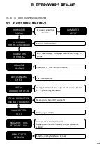
Page 43: ...es Switch on the unit switch If the unit asks you for a commissioning code note the serial number on the nameplate and contact your agent to obtain this code Enter your three digit code by doing this Press one of the keys 1 2 3 and the display will show you 0XX with the flashing zero to eventually change it by pressing 2 or 3 Once arrived at your digit validate it by pressing key 1 and your second...

Page 44: ...PRODUCTION XXX lbs h XXX kg hrs VALUE OF CTRL XX X V ROOM RH XX SET POINT XX RTH HC VERSION CODE If the tank is empty it displays that the tank filling is in process If Aquastat is ON Frost protection Test levels sensors During shutdown phases only and when water is below xx C preheating is enabled Steam production lbs h and kg h Display signal control Appears when a sensor is used Display of the ...

Page 45: ...TAL PRODUCTION XXXXX POWER CONSUMED XXX kW MAX POWER RATE XXX kW Means that the high limit switch is opened With RH sensor only it means that the RH sensor is not connected Steam Demand Remaining time without demand before end of season drain Service Timeout Time meter Produced kg counter Display power consumed Maximum power T L XXX C XXX F R XXX C XXX F Water temperature 1 Tank or 2 Tanks ...

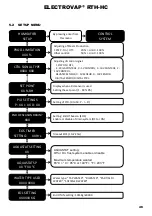
Page 46: ... Limit 100 SET POINT XX RH PID SETTINGS P XX I XX D XX END OF SEASON DRAIN XXX EOS TIMER SETTING XX Hrs Display when a RH sensor is used Setting the set point 1 99 Rh Setting of PID 0 to 50 P I D Setting End Of Season EOS Enable or disable of drain system OFF or ON Timeout EOS 1 to72 hrs AQUASTAT SETTING XX AQUASTAT SP XX F XX C WATER TYPE USED XXXX XXXX EOL SETTING XXXXXX KG AQUASTAT setting Off ...

Page 47: ...trol signal D Demand TX COM 1 RX COM 1 A1 LXXX C XXX F X RXXX C XXX F A2 NV VE TIMER X X A3 NV VE TIMER X X A4 LXXX C XXX F X RXXX C XXX F A1 Alarm Status A1 0 no fault 1 fault Water temperature for right left tank NC displayed if the sensor is not connected A2 Alarm status A2 0 no fault 1 fault LV Levels 0 1 2 et 3 FV Fill Valve 0 closed 1 opened TIMER Timeout Alarm A2 A3 Alarm status A3 0 no fau...

Page 48: ...Alarm status A7 0 no fault 1 fault LV Levels 0 1 2 et 3 FV Fill Valve 0 closed 1 opened TIMER Timeout Alarm A7 A8 Alarm status A8 0 no fault 1 fault LV Levels 0 1 2 et 3 FV Fill Valve 0 closed 1 opened TIMER Timeout Alarm A8 A9 Alarm status A9 0 no fault 1 fault LV Levels 0 1 2 et 3 FV Fill Valve 0 closed 1 opened TIMER Timeout Alarm A9 A10 Alarm status A10 0 no fault 1 fault LV Levels 0 1 2 et 3 ...

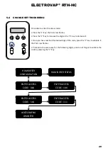
Page 49: ...ase it Once you have reached the desired digit of the code press the 1 key to validate it the 2nd cross flashes Proceed in the same way for the following digits and do not forget to validate the code by pressing the 1 key HUMIDIFIER CONFIGURATION HUMIDIFIER STATUS ENTER ACCESS CODE XXX ENTER ACCESS CODE 1XX ENTER ACCESS CODE 11X ENTER ACCESS CODE 111 ACCESS MENU GRANTED 5 1 2 3 4 ...

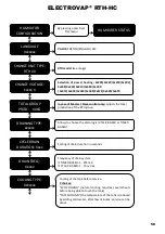
Page 50: ...BASED Setting of drain duration in seconds Frequency of drain system IF TIMED BASED 1 255 min IF CYCLIC BASED 1 10 cycles Cooling of the tank before service 2 choices ECO COOLING natural cooling requires several hours before being able to touch the tank FAST COOLING the temperature of the tank is reduced by adding cold water after few minutes service can be done Selection of power heating 2x200 2x...

Page 51: ...ORK UNIT ID XX COM SPEED XX bs Setting current time lost when power is off year Month day Hour Minute Factory testing date Month year read only Address unit network 1 ID 254 Communication network speed for RS485 2400 speed 230400 Calibration of the tank temperature sensor 5 at 5 For the RTH 2 tanks right temperature Only for RTH with 2 tanks only Calibration left temperature 5 at 5 COM PROTOCOL Xx...

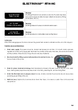
Page 52: ...s displayed when the M2 display is displayed and 100 hours have elapsed without maintenance Then the unit is shut down drained the tank cooled and put on hold of mandatory maintenance MANUAL DRAIN IN PROCESS This message is displayed once after pressing the manual drain button The drain is activated COOLING CYCLE IN PROCESS This means that the manual drain is complete and you must wait for the tan...

Page 53: ...ensor and the main board see wiring diagrams pg 29 Floats visual checking and cleaning if needed 3 Defective temperature sensor or calibration to be redone If this message appears when the tank is cold the temperature sensor PT100 must be tested and replaced if necessary Then contact your agent to recalibrate 4 Water quality issue Foam occurs in the tank the purging time must be increased From the...

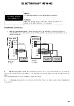
Page 54: ...Also check the condition of the water inlet valve the electrical connection and the condition of fuse F2 2A Change the valve and fuse if defective 2 Blue hose inside the filling cup incorrectly positioned or pinched Replace the hose as shown in the picture 3 Check for proper condensate drainage Must absolutely be drained otherwise it will accumulate in the steam hose creating water projections and...

Page 55: ...ctive temperature sensor Disconnect the temperature sensor from connector X04 Use a multimeter to measure the resistance value of the PT100 at room temperature and compare this value with the PT100 resistance table If the value is different the sensor is defective replace the sensor 3 Electronic issue Replace the main board and check that there is no steam or water flow in the electrical compartme...

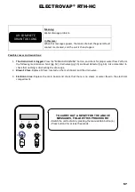
Page 56: ...hen this message appears the tank is drained the general fault contact is activated and the unit is stopped Possible causes and resolutions 1 Incorrect power supply Using a voltmeter check supply voltage Vac on terminals L1 L2 and L3 of the heating elements If the supply voltages are not identical check the supply circuit up to each heating element and replace the defective components 1 Continuous...

Page 57: ...aintenance tank pg 54 drain valve pg 55 and level detector pg 56 Also remember to check that nothing is obstructing the drain pipe 2 Blown F3 fuse Replace F3 fuse located on the main board and the drain valve 3 Electronic issue Replace the main board and check that there is no steam or water flow in the electrical compartment A9 COMPLETE DRAIN TOO LONG TO CARRY OUT A RESET FOR THE ABOVE MESSAGES F...

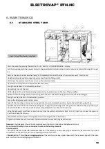
Page 58: ...p 4 Disconnect the pressure level hose and uncap the water level tank Unscrew the union junction to disconnect the drain hose Swing the tank down to intermediate position Unlock the 4 locks of the tank Lift the tank lid 7 mind the positioning marks and lay it upside down on the top of the humidifier Release the tank holding steel cord and swing down the tank the limescale deposit falls into the fl...

Page 59: ...ilter Check and clean if necessary the inside of the valve body by running water through the hole Reassemble the drain valve as original before repositioning the tank by proceeding as follows 1 Install the cleaned cover 2 Tilt back the tank 3 Install the chain and cap nut 4 Connect the drain valve 5 Install the steam hose and do not forget to tighten the hose clamp Ensure that all the clamps are p...

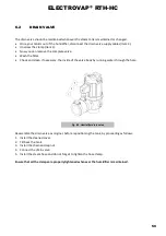
Page 60: ...e any particles Once all these operations completed please reassemble the unit taking care to check the condition of the water supply hose clamp You can put your appliance back into service Ensure that all the clamps are properly tightened whenever the humidifier is maintained 6 4 WATER LEVEL DETECTOR Maintenance of the detector should be done during each tank maintenance Disconnect the cables of ...

Page 61: ...ors 277V 1900W D110765 346 SP Electrical Resistors 346V 1900W D110765 398 SP Electrical Resistors 398V 1900W D110761 230 SP Electrical Resistors 230V 4300W D110761 277 SP Electrical Resistors 277V 4300W D110761 346 SP Electrical Resistors 346V 4300W D110761 398 SP Electrical Resistors 398V 4300W 8 D110747 SP T Water supply tank 9 D94061 SP Anti clogging system 10 D110750 SP 304L stainless steel ta...

Page 62: ...vel detector 1 D108231 SP Polypropylene upper body 2 D108237 SP Flat gasket for float set of 3 3 D80985 SP Level sensor set of 3 4 D110734 SP O ring seal 5 D108230 SP Stainless steel sensor support 6 D110735 SP Polypropylene lower body N Code Description 1 3 D99228 SP Complete valve 1 D108256 SP Adapter ring 2 D110205 SP Drain valve filter 3 D128002 SP Drain valve connector Fig 7 2 Water inlet val...

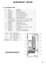
Page 63: ... 20 100 if Up v 230 600V D110806 690 75 SP Static relay RTH HC if Up v 690V 9 D50932 SP 24Vac Contactor 10 D110173 SP Setting terminal 115 230V 11 D110768 SP Fuse protection terminal 6mm 12 D110166 SP Stop terminal 13 D110128 50 SP Control transformer Prim 2x115V Sec 2x12V 14 D92393 SP On Off switch D116631 SP Fast Fuse 2A 5x20 mm Bag of 6 D116718 SP Fast fuse 5A 5x20 mm Bag of 6 Location Amp Fuse...

Page 64: ...ct features and specifications may change without notice RTH HC 03 21 Edition V 3 0 X program version 185 Boulevard des Frères Rousseau 76550 Offranville France www devatec com Export Tel 33 0 2 35 83 06 44 Email export devatec com France Tel 33 0 2 35 04 61 41 Email france devatec com ...

Reviews: