background image

ElectroVap RTH-V2

63

Pictures and values are not contractual - The devices  may be subject to changes without notice 

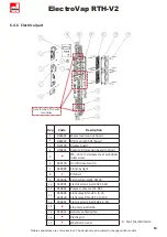
6.4.6   Electrical part

Only for the RTH 2 with 

two tanks

Rep

Code

Description

1

D92442

Water level control board 

2

D92949

RTH main CMS-0TI board 

3

D27109

Display board 

4

D50931

Remote information board (option) 

5

Ø4 - L8 mm stainless steel cylindrical          

head screw

6

930100

On/off rocket switch

7

930099

Stand-by light

8

DIN Rail

9

930096

Earth terminal JEK 35/35

10

930095

Electrical terminal JSAK 35 EN

11

930093

Power contactor LC1-D32

12

930528

930529

Static relay RTH-V2 5 to 15       

Static relay RTH-V2 20 to 100

13

930097

Electrical terminal JSAK 2.5 EN

14

Stop terminal GD35

15

930531

Helical ventilation fan

16

Plastic grid

17

Ø4x10 mm rivets

Not for retail sale

Summary of Contents for ElectroVap

Page 1: ...RESISTIVE STEAM HUMIDIFIER RTH 5 to 50 kg h TECHNICAL MANUAL ...

Page 2: ......

Page 3: ...ositioning 3 4 Steam outlet 3 5 BlowerPack fan unit 3 6 Drain water condensate draining 3 7 Water cooling kit option 3 8 Electrical connections 3 9 Temperature sensor connection 3 10 Control connection 11 11 13 14 20 21 22 23 24 34 38 4 SETTING UP 39 5 SOFTWARE ASSISTANT 5 1 Information menu 5 2 Setup menu 5 3 Control system menu 5 4 Change settings menu 5 5 Maintenance alerts 5 6 Fault messages 4...

Page 4: ...nts the negligence of this warning can lead to serious bodily injury or death to people and or significant material malfunctions Danger of scalding The ExpressPack uses steam during the operation and therefore surfaces and pipe work become very hot Ensure that equipment not sustaining high temperatures is kept away Electrostatic hazard The components of the device may be subject to deterioration a...

Page 5: ...emical into the hydraulic system Make sure that the water supply pressure does not exceed 6 bar Always be careful that the installation meets local standards electricity The user ensures that electrical installation will be carried out by an authorized technician in this field The installer has to provide the correct cable section as well as the magnethermic circuit breaker protection warranty Dev...

Page 6: ...60335 2 88 EN 55022 classe B EN 60204 1 EN 61000 4 2 EN 61000 4 3 EN 61000 4 4 EN 61000 4 5 EN 61000 4 6 EN 61000 6 2 EN 61000 6 3 We the undersigned hereby declare that the equipment specified above conforms to the above Directive s and Standard s FRAMBOT Jean François General Manager 16 10 2018 1 4 RoHS DECLARATION Devatec Confirms that the BlowerPack fan unit is manufactured in compliance with ...

Page 7: ...FF thread with washers for tap water connection 3 1 50 m long Ø40 mm drain hose 4 3 hose clamps 2 for the steam hose and 1 for the drain hose 5 Cardboard drilling template 6 1 limescale collecting bag supplied with each order 2 Product presentation Do not throw away the cardboard drilling template supplied with the unit OPTIONS Remote information board Filling cup platform 400 230V transformer for...

Page 8: ...485 E Steam outlet Side view 176 F Tank draining Front view 730 G Tank draining Side view 175 H Water inlet Face 710 I Water inlet Side view 310 L Electrical wire outlet diameter 40 2x16 M Steam outlet 2 N Overflow draining Front view 772 O Overflow draining Side view 304 kg Weight in operation 75 Gross weight packed 45 RAL7035 powder coated metal case 2 2 DIMENSIONS Front Side ...

Page 9: ...g cup 5 Ø18x22 mm overflow hose 6 Water inlet valve 7 Display board 8 Main PCB board Transformer 9 Water level management board 10 Remote information board 11 Stand by lamp 12 On Off switch 13 Power contactor 14 Wire tunnel 15 Fan 16 Tank 17 Resistor 18 Anti limestone system 19 Drain valve 20 Water level detector 21 Flexible braided hose with 3 4 FF thread 2 3 HUMDIFIER COMPONENT PARTS ...

Page 10: ... the device is not made of a heat sensitive material Wall mounting Please be careful that the support material receiving the device pillar wall etc is able to support it Fixation use a fastening system adapted to the support material Make sure that the mounting distances are met Please read and follow the enclosed safety information and the warning labels inside the humidifier before installation ...

Page 11: ...owels let them protrude by about 10 mm Hang the device on the upper screws screw without blocking Untighten slightly the screwing knob Fig 1_point 1 Tilt the stainless steel tank up to tighten the tank holding chain Fig 1_points 2 3 Take the water sensor wires off the water level detector Fig 1_point 4 Untighten the clamp holding the water level pressure hose and remove the latter from the cover o...

Page 12: ...screws After tightening the screws Tip the tank back to intermediate position and attach the tank holding chain Put the tank cover back and lock it with the 4 fasteners Set the humidifier tank back to upright position and screw up knob 1 Reconnect the high water level wires black wire with black wire white wire with white wire Set the humidifier tank back to upright position and screw up knob 1 Fi...

Page 13: ...1 Water recommendations The device is designed to be used with Potable water According to 98 83 EEC directive TH must be less than 40 fH and higher than 30 µS cm Natural Soft water If water conductivity is higher than 30 µS cm use an electrode level sensor standard potable water If water conductivity is lower than 30 µS cm use a float water level sensor Demineralized water water conductivity is lo...

Page 14: ... 1 Selection of steam dispersion tube 100 mm L1 Øa Øb Dispersion tube for RTH 5 20 Øa 40mm Øb 8 mm Requires Ø60 40mm reduction L1 mm Duct width MIN MAX D40 L290 290 300 599 D40 L590 590 600 799 D40 L790 790 800 1009 D40 L1000 1000 1010 1259 D40 L1250 1250 1260 1509 D40 L1500 1500 1510 Dispersion tube for RTH 30 50 Øa 60mm Øb 13 mm L1 mm Duct width MIN MAX DL 1 254 264 416 DL 1 5 407 417 568 DL 2 5...

Page 15: ...s and 4 nuts The length of the screws will depend on the thickness of the ventilation duct wall Step 2 Installation at the end of the tube into the duct Fixed by a Ø5 mm threaded rod passing through the hole provided for this purpose and passing through the duct wall To fix the whole structure 2 Ø5 mm nuts will be enough Fig 3 3 3 2 Dispersion tubes mounting For ensuring the best steam dispersion ...

Page 16: ...n this absorption distance the steam is still visible in the air stream in the form of fog If any furnitures are placed in this area condensate may form on them For this reason it is imperative to take into account this absorption distance when placing the humidifiers 3 3 4 How to calculate absorption distance D In order to determine the evaporation distance the attached calculation table can be u...

Page 17: ...e an air opening before a humidity sensor A high humidity limit humidistat must be installed in the duct to stop the humidifier in case the level of humidity exceeds the preset value If the recommended distances cannot be met please contact Devatec or their authorized agent for an alternative solution Make sure the distances are met if this is not possible please contact your Devatec agent 3 3 6 M...

Page 18: ...le of the steam pipe H2 140 mm minimum for a standard mounting 110 mm minimum for a stair mounting H3 160 mm Minimum height between the axle of the dispersion tube and the top of the duct wall The H3 distance can be 80 mm at the shortest if the steam pipe is installed at a 30 angle The arrow shows the direction of the air flow H 380 mm H 490 mm H 270 mm H 410 mm H 550 mm ...

Page 19: ...o changes without notice In vertical ducts where the air flow is upward or downward the steam distribution pipe s must be tilted by 15 sideways In duct with limited height the distribution pipe s can be tilted by 30 to get the 80 mm minimum height d Duct diameter D Humidification distance D ...

Page 20: ...a correct installation Ø40 or Ø60 mm steam hose max 3 m length Stainless steel or copper pipe with a slightly larger diameter connected to the ground Use a flexible steam hose cuff to connect the humidifier to the steam distribution pipe The length of the hose must not exceed 6 m and must be insulated Make sure that the steam hose is not leaky or does not form a water pocket Failure to follow thes...

Page 21: ...e humidifier BlowerPack electrical wiring must be done on terminals 3 4 on the DIN rail of the humidifier As far as the EHF 3 is concerned please revert to the recommendations given on the EHF 3 information sheet Never connect the EHF 3 unit on the terminals 3 4 of the humidifier when a 100 VA transformer is installed inside the ElectroVap RTH humidifier Allow a 3 m distance ahead to the fan unit ...

Page 22: ... has water collecting facilities option on request s a drawings 1 2 5 A funnel can also be used s a pict 2 but it should be offset from the underside of the unit to prevent any steam and or condensation from getting into the cabinet The installation of a siphon as per the draining hose is recommended and arrangements for holding water spilling should also be made 6 CAUTION keep a minimum pitch of ...

Page 23: ...ing kit opens and cold water is injected into the tube 11 allowing the drain water to cool 3 7 2 Installation The water cooling kit option it is installed on the water inlet valve through a 3 4 plastic connection 4 while the other side is installed on the drain valve through a 1 1 2 plastic connection 12 the electrical connection for the valve 7 The cooling inlet valve is electrically supplied by ...

Page 24: ...nges without notice 3 8 ELECTRICAL CONNECTIONS All work on the electrical parts must be carried out by qualified and authorized personnel In addition before making any electrical connections check that your installation has been determined from the values in the table above 3 8 1 Technical data ...

Page 25: ...ectric shock can be fatal it is necessary to install circuit breakers Q1 2 pôles 2A L2 L1 N L3 L PE The symbol Δ between Q1 Q2 means that these MCB are coupled The power MCB Q2 and control MCB Q1 are mechanically linked together So if a fault is detected the power and the control circuits are switched off and there is no voltage on the unit The unit is really off voltage D 3 phases without neutral...

Page 26: ...changes without notice L2 L1 N L3 L PE T L2 L1 N L3 L PE E U 3x208 220 230V F U 3x440 460 480 575 600V RTH 8 36 Q2 3 poles Q1 2 poles 2A Power in 3x 208 230V 50 60Hz GROUND RTH 7 50 GROUND Q2 3 poles Q1 2 poles Power in 3x xxx VAC 50 60Hz T Transformer prim 460V sec 230V S 100 VA see page 27 ...

Page 27: ...ransformer option that allows at lower cost to replace a neutral line 1 2 3 4 15V 0V 15V 230V 400V J1 J2 J3 J4 42 42 41 41 39 39 40 40 L2 L1 N L3 L PE RTH 7 50 External power protection Power 3x380 400VAC Primary circuit protection Transformer Prim 400V Sec 230V L2 L1 N L3 L PE F2 2A F1 T RTH 7 50 External power protection Power 3x XXX VAC 50 60Hz T Transformer Prim XXX V Sec 230V WITH NEUTRAL I T...

Page 28: ...m production dry contact X21 connector 33 34 35 Remote general fault dry contact X20 connector 30 31 32 Remote tank maintenance dry contact 30 31 32 33 34 35 36 37 38 The connection of the options below must be done with a flexible cable of 0 75 mm maximum 3 8 4 RS485 HARDWARE CONNECTION The RS485 connection must be plugged on the J1 connector Terminal 1 Data Terminal 2 Data Terminal 3 Signal Grou...

Page 29: ...y of humidifiers The requests passing on the BUS must in no case exceed 15 bytes ModBus RTU Bacnet MSTP Communication speed 2400 4800 7200 9600 14400 19200 28800 38400 57600 115200 230400 bauds Defaut 9600 Packet size 8 bits Parity NON Stop bit 2 1 Timeout response 5000ms 5sec Time between requests after response received Min 100ms standard Nb of registers per request 5 maxi 3 8 6 COMMUNICATION PR...

Page 30: ......

Page 31: ...ay be subject to changes without notice 3 8 7 WIRING DIAGRAMS Rep Amperage Fuse function F1 2A Protection of power contactor coil F2 2A Protection of the inlet valve coil F3 2A Protection of the drain valve coil F4 100 mA Protection of the electronic boards RTH 5 8 MONOPHASE ...

Page 32: ...ElectroVap RTH V2 32 Pictures and values are not contractual The devices may be subject to changes without notice RTH 5 40 THREE PHASE ...

Page 33: ...ElectroVap RTH V2 33 Pictures and values are not contractual The devices may be subject to changes without notice RTH 45 50 THREE PHASE ...

Page 34: ...T C 180 mm RTH R8 R9 8 4 3KW 230V 1 9KW 230V Emplacement sonde de température Humidity sensor location L2 HUMIDIFIER RTH 8 1X230V Butée 4 A2 3 A1 2 T1 1 L1 Butée S1 COUVERCLE VUE DE DESSUS LID TOP VIEW 8 70 72 73 17 8 N1 L PE PE N L1 3 Butée 4 T C A1 73 17 14NO A2 6T3 4T2 13NO 3L2 5L3 K1 2T1 1L1 70 A2 72 PE Butée 2 1 Façade appareil Front Unit R8 T C T C 180 mm R8 T C RTH R8 5 4 3KW 230V Emplaceme...

Page 35: ...4 18 T C 14NO A2 4T2 6T3 2T1 13NO 1L1 K1 3L2 5L3 A2 A1 PE Butée 2 1 Façade appareil Front Unit R8 T C T C 180 mm S1 Butée 2 T1 1 L1 4 A2 3 A1 4 A2 3 A1 2 T1 1 L1 Butée S2 COUVERCLE VUE DE DESSUS LID TOP VIEW Butée 6 10 13 17 14 68 70 72 68 70 72 73 74 74 73 P2 2 13 14 3 4 15 10 4 R1 R4 R9 R8 T C R2 R6 8 17 18 9 P1 15 3 2 8 6 9 L2 L PE PE L3 N L1 3 Butée 4 18 T C 14NO A2 4T2 6T3 2T1 13NO 1L1 K1 3L2...

Page 36: ... 230V 1 9KW 230V 4 3KW 230V 1 9KW 230V 4 3KW 230V 1 9KW 230V 4 3KW 230V 4 3KW 230V 50 4 3KW 230V 4 3KW 230V 4 3KW 230V 4 3KW 230V 4 3KW 230V 4 3KW 230V 4 3KW 230V 4 3KW 230V 4 3KW 230V S1 Butée 2 T1 1 L1 4 A2 3 A1 4 A2 3 A1 2 T1 1 L1 Butée S2 COUVERCLE VUE DE DESSUS LID TOP VIEW Butée 1 7 6 12 5 10 11 13 17 14 75 76 77 75 76 77 73 74 74 73 P3 P2 2 13 14 3 4 15 10 4 R5 R1 R4 R9 R8 T C R3 R2 R7 R6 1...

Page 37: ...cordements détecteur de niveaux d eau à électrodes Raccordements détecteur de niveaux d eau flotteurs Numéros sur platine de gestion des niveaux réf 500852 4 500852 4 500852 4 3 9 1 Water level management board RTH with 1 or 2 contactors S1 S2 Electrode Water Level Sensor Connections Numbers on the water management board réf 500852 4 Float water level connection White wire Blue wire ...

Page 38: ... on 1 2 3 4 S1 on 1 2 3 4 V g Rh 1 2 Sensor devatec Sensor 0 _ 5 V 1 2 connection control humidistat high level safety humidistat or and duct pressure switch don t put voltage on terminals 1 2 Humidity sensor devatec SW2 Dip Switch allows to choose desired regulation see configuration below 3 10 CONTROL CONNECTION The wiring of the optional equipment must be made with 0 75 mm2 flexible cable This ...

Page 39: ... rocker switch The display will default to show the rate of steam produced You are in the user information menu Enter your 3 digit code as follows Press one of the button and the display will show you 0XX with the flashing zero to eventually change it by pressing or Once arrived at your digit validate it by pressing the button and your second digit flashing Repeat the previous 2 operations to disp...

Page 40: ... TANK IN PROCESS HUMIDIFIER SETUP VALUE OF CTRL XX X V ROOM RH XX SET POINT XX ou ou ou ou RTH VERSION CODE If the tank is empty it displays that the tank filling is in process If Aquastat is ON Frost protection Test levels sensors During shutdown phases only and when water is below xx C preheating is enabled Steam production lbs h et kg h Display signal control Appears when a sensor is used Displ...

Page 41: ...TION TO EOL XXXX kg ou ou ou Stop the unit by Modbus or Bacnet Means that the high limit switch is opened With RH sensor only it means that the RH sensor is not connected Steam Demand Water temperature Service Timeout Time meter MAX POWER RATE XXX kw TOTAL PRODUCTION XXXXX kgs POWER CONSUMED XXX kw Produced kg counter Display power consumed Maximum power or or or TIME REMAINING TO EOS XXXX hrs Rem...

Page 42: ...ROL SYSTEM Adjusting of Steam Production 1 STEP On Off 20 Limit 100 Other control 50 Limit 100 Adjusting of control signal 1 STEP ON OFF 4 20mA CONTROL 0 5V CONTROL 0 10V CONTROL 2 10V CONTROL DEVATEC SENSOR 0 5V SENSOR 0 10V SENSOR DIGITAL SENSOR DIGITAL CTRL 5 2 SETUP MENU Display when a RH sensor is used Setting the set point 1 to 99 Rh Setting of PID 0 to 50 P I D Setting End Of Season EOS Ena...

Page 43: ...t notice WATER TYPE USED XXXX XXXX AQUASTAT SETTING XX AQUASTAT SP XX F XX C EOL SETTING XXXXXX KG AQUASTAT setting Off or On frost system enable or disable Maximum temperature wanted 65 C C 95 C or 149 F F 203 F End Of Life setting 100 Kg 20000 Water type TAP WATER DI WATER PARTIAL DI WATER SOFTENED WATER ...

Page 44: ...ure for right left tank NC displayed if the sensor is not connected TX COM 1 RX COM 1 A2 LV FV TIMER X X X X A3 LV FV TIMER X X X X A2 Alarm status A2 0 no fault 1 fault LV Levels 0 1 2 et 3 FV Fill Valve 0 closed 1 opened TIMER Timeout Alarm A2 A3 Alarm status A2 0 no fault 1 fault LV Levels 0 1 2 et 3 FV Fill Valve 0 closed 1 opened TIMER Timeout Alarm A3 NS Network Bus 0 Stop 1 Run HLS High Lim...

Page 45: ...ER Timeout Alarm A6 A7 Alarm status A2 0 no fault 1 fault LV Levels 0 1 2 et 3 FV Fill Valve 0 closed 1 opened TIMER Timeout Alarm A7 A8 Alarm status A2 0 no fault 1 fault LV Levels 0 1 2 et 3 FV Fill Valve 0 closed 1 opened TIMER Timeout Alarm A8 A9 Alarm status A2 0 no fault 1 fault LV Levels 0 1 2 et 3 FV Drain Valve 0 closed 1 opened TIMER Timeout Alarm A9 A10 LV FV TIMER X X X X A10 Alarm sta...

Page 46: ...mber or the 3 key to decrease it Once you have reached the desired number of the code press the 1 key to validate it the 2nd cross flashes Proceed in the same way for the following numbers and do not forget to validate the code by pressing the 1 key HUMIDIFIER CONFIGURATION ENTER ACCESS CODE XXX HUMIDIFIER STATUS ENTER ACCESS CODE 1XX ENTER ACCESS CODE 11X ENTER ACCESS CODE 111 ACCESS MENU GRANTED...

Page 47: ...he tank before service 2 choices ECO COOLING natural cooling requires several hours before being able to touch the tank FAST COOLING the temperature of the tank is reduced by adding cold water after few minutes the service can be done CHANGE UNIT TYPE RTH XX HUMIDIFIER CONFIGURATION LANGUAGE XXXX CHANGE VOLTAGE X XXX V FRANCAIS ENGLISH RTH model see range Selection of power heating 2x220 2x230 3x2...

Page 48: ...SPEED XX bs COM PROTOCOL Start up of self checking system YES or NO Calibration of control signal 10 at 10 Calibration of the tank temperature sensor 5 at 5 For the RTH 2 tanks righ temperature Only for RTH with 2 tanks only Calibration left temperature 5 at 5 Setting current time optional battery year Month day Hour Minute Setting the date test Month year Adress unit network 1 ID 254 Communicatio...

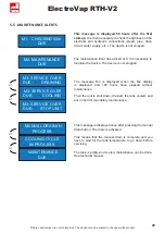
Page 49: ...MAINTENANCE ALERTS COOLING CYCLE IN PROCESS MAINTENANCE DUE MANUAL DRAIN IN PROCESS ou ou This message is displayed once after pressing the manual drain button The drain is activated This means that the manual drain is complete and you have to wait for the tank temperature to go down before servicing The tank is empty and cooled maintenance can be done See technical manual or or M3 SERVICE OVER DU...

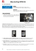
Page 50: ...must be no short circuit between these In addition check the quality of these electrodes or floats as well as the cleanliness of the bottom of the detector cover nothing should connect the electrodes together In the case of a float water level detector DI version demineralized water check that none of the floats fail 3 Faulty temperature sensor or calibration to redo If this message appears while ...

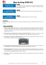
Page 51: ... condition of the inlet valve the electrical connection and the state of the F2 fuse 2AT If out of service replace valve and fuse 2 The blue hose into the filling cup is incorrectly positioned or folded The blue hose must have one end in the water feed hole and the other in the middle hole If the hose is folded please change it 3 Check that the condensate is drained properly Condensate has to be e...

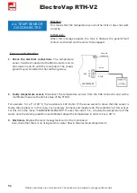
Page 52: ...ed to the card fixing screw 2 Faulty temperature sensor Disconnect the temperature sensor from the X04 connector and with a multimeter measure the ohmic value of the PT100 For example for a T of 20 C the resistance is 107 8 ohm If the value seems to prove that the sensor is faulty then replace it In this case it is necessary to check and maybe redo the calibration of this sensor For this from the ...

Page 53: ...dies 1 Problem with the level detector Check the electrical connection between the electrodes and the level control board See the electrical diagrams Check that there is no water on the sensor cover between the electrodes e g good fixation of the steam pipe Disassemble the upper part of the detector and check the cleanliness See below Also check the cleanliness of the water supply port located at ...

Page 54: ... P bar 6 replace the inlets valve if necessary 3 Water level detector Check that the level sensor detector and the pressure balancing hose are clean and that nothing prevents the water from circulating Also check the electrical connections between the level sensor the level management board and the main board 4 Disjunction of the power circuit OFF Two possible causes Differential switching off in ...

Page 55: ...en stopped Causes and remedies 1 The drain circuit is clogged Press the MANUAL DRAIN button and check if the water is flowing Clean the inside of the tank the pressure balancing hose and the water level sensor Also remember to check that nothing obstructs the sewer pipe Replace the tank gasket and if necessary the filter inside the drain valve 2 Electronics Replace the level management card or the...

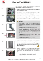
Page 56: ...with the rock button Fig 1 3 Remove the door and unscrew the clamps Completely remove the steam hose Fig 2 and remove it from the device 4 Unscrew the black knob located in the lower part of the tank Uncouple the drain hose by loosening the union Fig 3 a and the water supply hose on the tank Fig 3 b 5 Now you can tilt the tank to its intermediate position Fig 4 6 Detach the 4 closing clips of the ...

Page 57: ...o put it back in the initial position and check there is no wire trapped between the tank and the device bottom The wires supplying the resistors must be replaced in the cable clamp provided for this purpose see Fig 12 5 Wipe the 4 high water level electrodes and put back the high water level electrode set Swing the tank up s a picture n 11 Tighten up the black knob and reconnect the drain and ste...

Page 58: ...move it Take care do not attempt to unscrew the black flutted tee assembly 4 watertightness originally ensured by sealing glue Without unscrewing clean the water supply circuit between the detector and the tank 4 IN CASE OF A WATER LEVEL DETECTOR HAVING ELECTRODE SENSORS Unscrew the 3 screws 5 to get access to the sensor elements Notice do not use solvent to clean up the water level housing If nee...

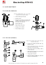
Page 59: ...e body 5 Wash the filter 6 Reassemble all the parts Change parts if needed Tilt coil holder 1 back 6 3 2 Inlet valve maintenance TURN OFF THE WATER SUPPLY FIRST AND THEN TURN THE DEVICE OFF Unscrew the flexible braided hose 1 then the nut 2 Remove the filter 3 with a small clamp and wash it with clean water Take out the coil 4 by tilting it with a small screwdriver Wash with clear water the valve ...

Page 60: ...D36279 930547 930543 D36280 930548 930544 Electrical Resistors 1 9 Kw 230V Electrical Resistors 1 9 Kw 277V Electrical Resistors 1 9 Kw 346V Electrical Resistors 4 3 Kw 230V Electrical Resistors 4 3 Kw 277V Electrical Resistors 4 3 Kw 346V 3 930505 Metal stuffing box PG7 4 Tip M1 4 Ø8 mm 5 D36282 Tank gasket 6 Capnut M8 7 Knurled knob M8 8 500311627 500513227 Water level detector union 9 D110742 B...

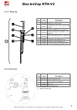
Page 61: ...i buble blue hose inside filling cup 3 930520 Overflow Ø18x22 mm Lg115 cm 4 930518 Water feeding hose Ø18x22 mm Lg36 cm 5 930517 Water hose Ø12x16 mm Lg33 5 cm 6 930081 Tightening clamp Ø12x22 mm 7 930082 Tightening clamp Ø16x27 mm 8 930515 Complete filling cup RTH60 to100 Rep Code Description 1 930160 Water inlet valve coil 2 Water inlet valve body N2 3 930224 3 4 nut 4 D36284 Water inlet valve N...

Page 62: ...ng Ø88x3 mm 3 930587 Water level sensors set of 4 4 eyelet terminal 5 Stainless steel bolt Ø4 mm 6 Self thread screw Ø3 9 L 13 mm 7 Stainless steel screw Ø4 L 8 mm 8 Fiber gasket 9 Float sensor 10 930584 Water level set RTH V2 DI Not for retail sale Rep Code Description 1 Steam hose Ø40 mm L 60 mm 2 930302 Tightening clamp Ø40X60 mm 3 930570 Membrane kit stem Muller cover 4 930537 Drain valve filt...

Page 63: ...931 Remote information board option 5 Ø4 L8 mm stainless steel cylindrical head screw 6 930100 On off rocket switch 7 930099 Stand by light 8 DIN Rail 9 930096 Earth terminal JEK 35 35 10 930095 Electrical terminal JSAK 35 EN 11 930093 Power contactor LC1 D32 12 930528 930529 Static relay RTH V2 5 to 15 Static relay RTH V2 20 to 100 13 930097 Electrical terminal JSAK 2 5 EN 14 Stop terminal GD35 1...

Page 64: ... change without prior notice RTH V2 tech edition 10 2019 For program version V3 0 X 185 Boulevard des Frères Rousseau 76550 Offranville France Division export Division france LR 94104 2 tel 33 0 2 35 83 06 44 Email export devatec com www devatec com tel 02 35 04 61 41 Email france devatec com www devatec com ...

Reviews: