D-39
(10) Scanner’s Sub-Scanning Registration Adjustment
<Requirement>
Perform this adjustment in the following cases.
•
After the Scanner Assy. has been replaced
•
After the printer’s main scanning & sub-scanning registration adjustments and the scan-
ner's sub-scanning zoom ratio adjustment have been performed
<Adjustment Procedure>
1. Print the test pattern.
2. Enter the “ADJUST” menu in the Service mode.
3. Place the test pattern on the Original Glass and make a test copy.
NOTES
•
The test pattern should be positioned vertically.
•
Use A4 L or Letter L paper loaded into Tray1 to make the test copy.
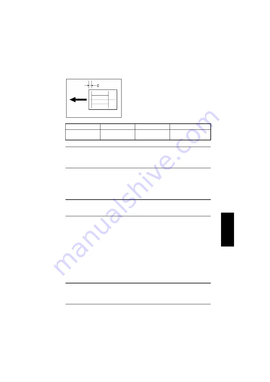
4. Check that the width of C in copy of the test pattern meets the specification.
If the width of C is out of specification, adjust it according to the following procedure.
5. Change the setting.
If the width of C in the test pattern is longer than the specified width . . . . . Increase the set-
ting.
If the width of C in the test pattern is shorter than the specified width . . . . . Decrease the
setting.
✽
If the shift cannot be adjusted to within the specification with a single adjustment, perform
the adjustment again to change the setting.
6. Press the Yes key to apply the setting.
NOTE
If the Stop key is pressed, instead of the Yes key, the main screen is displayed and the set-
ting returns to that before it was changed.
Place the test pattern on the Original Glass again, make another test copy, and check it.
Specification
Mode
Function Item
Setting Range
20±3.0 mm
“ADJUST” menu
CCD SUB REGIST
90 to 110
1 increment = 0.5 mm
• After finishing the printer’s main scanning & sub-
scanning registration adjustments, place the
printed test pattern on the Original Glass, and
make a copy of it.
• Adjust the width of C in the copy of the test pattern
so that the following specification is met.
4007D051AA
Summary of Contents for D 16G
Page 1: ...DEVELOP SERVICE MANUAL OPTIONS D 16G 4986 7991 00 ...
Page 2: ......
Page 4: ......
Page 10: ......
Page 11: ...GENERAL ...
Page 12: ......
Page 20: ......
Page 21: ...MECHANICAL ELECTRICAL ...
Page 22: ......
Page 54: ......
Page 55: ...MAINTENANCE ...
Page 56: ......
Page 66: ......
Page 67: ...DIS REASSEMBLY ADJUSTMENT ...
Page 68: ......
Page 116: ......
Page 117: ...CONTROL PANEL SERVICE MODE DESCRIPTIONS ...
Page 118: ......
Page 122: ...S 4 2 3 PWB IF Interface Board 4980S004AA USB port IEEE1284 parallel port ...
Page 142: ......
Page 143: ...TROUBLESHOOTING ...
Page 144: ......
Page 184: ...DEVELOP Copyright 2003 Develop Printed in Germany ...
Page 185: ...AF 11 Service Manual ...
Page 188: ...GENERAL ...
Page 190: ...MECHANICAL ELECTRICAL ...
Page 199: ...DIS REASSEMBLY ADJUSTMENT ...
Page 215: ...TROUBLESHOOTING ...
Page 224: ...PF 125 Service Manual ...
Page 226: ...GENERAL ...
Page 228: ...MECHANICAL ELECTRICAL ...
Page 233: ...DIS REASSEMBLY ADJUSTMENT ...


