S-12
4-3.
Service Mode Functions
(1)
Service's Choice
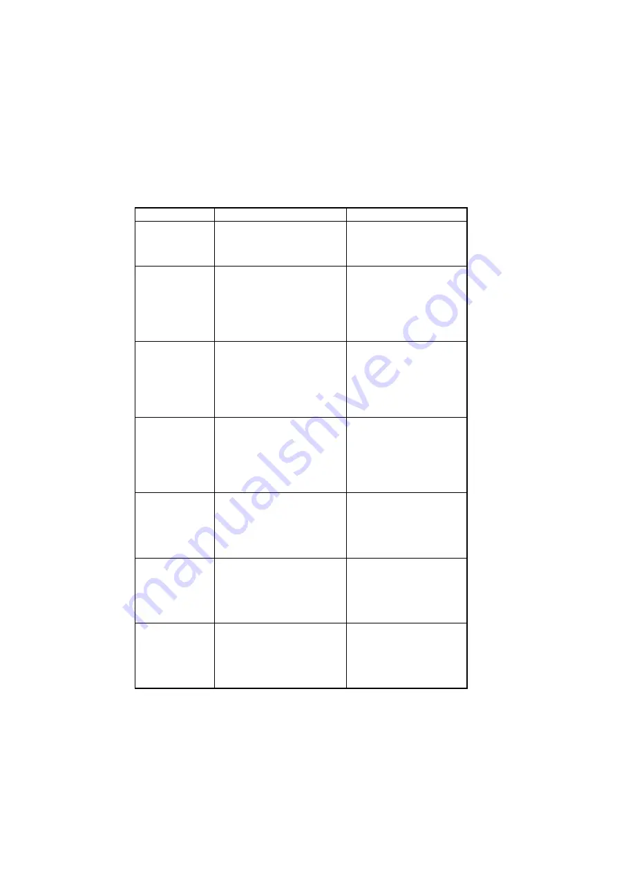
• Various machine service functions can be specified.
Function
Purpose
Setting Details/Precautions
SHIPMENT
DESTINATION
To switch the fixed zoom ratios and
paper sizes according to the
selected marketing area.
• The default setting is either
“METRIC” or “INCH”.
METRIC
INCH
LEADING EDGE
ERASE
To change the laser emission tim-
ing to adjust the width of the image
area that is erased at the leading
edge.
✽
When the PH unit has been
replaced
• The default setting is “4mm”.
0mm 1mm 2mm 3mm 4mm 5mm
TRAILING EDGE
ERASE
To change the laser emission tim-
ing to adjust the width of the image
area that is erased at the trailing
edge.
✽
When the PH unit has been
replaced
• The default setting is “4mm”.
0mm 1mm 2mm 3mm 4mm 5mm
VERTICAL EDGE
ERASE
To change the laser emission tim-
ing to adjust the width of the image
area that is erased on both sides
(CD direction).
✽
When the PH unit has been
replaced
Select the value for the width
erased in the CD direction. (The
default setting is “4mm”.)
0mm 1mm 2mm 3mm 4mm 5mm
FLS PAPER SIZE
To specify the paper size for
foolscap.
✽
When the FLS paper size has
been changed
✽
Upon setup
• The default setting is
“330
∗
210”.
330
∗
203
330
∗
210
330
∗
216
337
∗
206
GDI TIMEOUT
To specify the time for GDI timeout • The default setting is “6” (60
seconds).
0 (5sec.) 1 (10sec.) 2 (20sec.)
3 (30sec.) 4 (40sec.) 5 (50sec.)
6 (60sec.)
TONER EMPTY
STOP
To select if copy operations are
stopped when the toner becomes
empty.
• The default setting is “ON”.
ON
OFF
• If “OFF” is selected, opera-
tions are not stopped when
the toner becomes empty.
Summary of Contents for D 16G
Page 1: ...DEVELOP SERVICE MANUAL OPTIONS D 16G 4986 7991 00 ...
Page 2: ......
Page 4: ......
Page 10: ......
Page 11: ...GENERAL ...
Page 12: ......
Page 20: ......
Page 21: ...MECHANICAL ELECTRICAL ...
Page 22: ......
Page 54: ......
Page 55: ...MAINTENANCE ...
Page 56: ......
Page 66: ......
Page 67: ...DIS REASSEMBLY ADJUSTMENT ...
Page 68: ......
Page 116: ......
Page 117: ...CONTROL PANEL SERVICE MODE DESCRIPTIONS ...
Page 118: ......
Page 122: ...S 4 2 3 PWB IF Interface Board 4980S004AA USB port IEEE1284 parallel port ...
Page 142: ......
Page 143: ...TROUBLESHOOTING ...
Page 144: ......
Page 184: ...DEVELOP Copyright 2003 Develop Printed in Germany ...
Page 185: ...AF 11 Service Manual ...
Page 188: ...GENERAL ...
Page 190: ...MECHANICAL ELECTRICAL ...
Page 199: ...DIS REASSEMBLY ADJUSTMENT ...
Page 215: ...TROUBLESHOOTING ...
Page 224: ...PF 125 Service Manual ...
Page 226: ...GENERAL ...
Page 228: ...MECHANICAL ELECTRICAL ...
Page 233: ...DIS REASSEMBLY ADJUSTMENT ...


