D-26
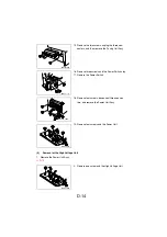
Look at the stop position of the Take-Up Roller from Clutch Gear side.
(6)
Disassembly of the Fusing Unit
NOTE
•
The Fusing Unit is extremely hot immediately after the Power Switch has been turned
OFF. Allow a sufficient time to let it cool down before starting the procedure to prevent
burn.
1. Remove the Fusing Unit.
☞
D-8
After setting replaced Paper Take-Up Clutch Gear
(Torque Limiter) to the shaft, Rotate the Paper Take-
Up Clutch Gear by hand (Need to be released Sole-
noid Flapper).
4136D060AA
1. When the Roller is leant to clockwise, move the
coupling Gear to A direction.
4136D046AA
2. When the Roller is leant to counter clockwise,
move the coupling Gear to B direction.
4136D045AA
2. Remove the two screws, and then the Fusing
Unit is divided into the Upper Fusing Roller sec-
tion and Lower Fusing Roller section.
4136D021AA
Upper Fusing
Roller section
Lower Fusing
Roller section
Summary of Contents for D 16G
Page 1: ...DEVELOP SERVICE MANUAL OPTIONS D 16G 4986 7991 00 ...
Page 2: ......
Page 4: ......
Page 10: ......
Page 11: ...GENERAL ...
Page 12: ......
Page 20: ......
Page 21: ...MECHANICAL ELECTRICAL ...
Page 22: ......
Page 54: ......
Page 55: ...MAINTENANCE ...
Page 56: ......
Page 66: ......
Page 67: ...DIS REASSEMBLY ADJUSTMENT ...
Page 68: ......
Page 116: ......
Page 117: ...CONTROL PANEL SERVICE MODE DESCRIPTIONS ...
Page 118: ......
Page 122: ...S 4 2 3 PWB IF Interface Board 4980S004AA USB port IEEE1284 parallel port ...
Page 142: ......
Page 143: ...TROUBLESHOOTING ...
Page 144: ......
Page 184: ...DEVELOP Copyright 2003 Develop Printed in Germany ...
Page 185: ...AF 11 Service Manual ...
Page 188: ...GENERAL ...
Page 190: ...MECHANICAL ELECTRICAL ...
Page 199: ...DIS REASSEMBLY ADJUSTMENT ...
Page 215: ...TROUBLESHOOTING ...
Page 224: ...PF 125 Service Manual ...
Page 226: ...GENERAL ...
Page 228: ...MECHANICAL ELECTRICAL ...
Page 233: ...DIS REASSEMBLY ADJUSTMENT ...


