Field Service Ver. 1.0 Apr. 2005
10. Service Mode
97
ineo 161
ineo 210
Adjustment / Setting
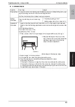
L. ADF REG. LOOP2
✽
appears only when the Duplexing Document Feeder (DF-605: ineo 210 only) is installed
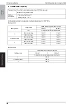
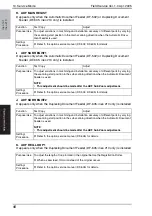
M. ATDC GAIN
N. MODEL SETTING
10.3.3
COUNTER
• COUNTER displays the counts of various counters.
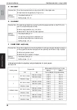
A. TOTAL COUNTER
B. SIZE COUNTER
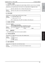
Purpose/Use
To adjust the length of loop formed in the original before the Registration Roller.
✽
When a skew feed, fold, or misfeed of the original occurs
Setting/
Procedure
✽
Refer to the option service manual (DF-605) for details.
Purpose/Use
To manually adjust the ATDC Sensor voltage.
Setting/
Procedure
• The default setting is “155.”
Setting range: 123 to 186
✽
The adjusted value of the ATDC Auto Adjust is the setting value.
Purpose/Use
NOTE
Never change this setting.
If it is changed, the Tech. Rep. call (C03FF) will appear.
Setting/
Procedure
✽
Default setting depend on the marketing area setting.
20 ppm
18 ppm
16 ppm
Purpose/Use
To display the total count value of the selected mode.
Setting/
Procedure
1: COPY
2: COPY DUPLEX
3: PRINT
4: PRINT DUPLEX
Purpose/Use
To display the count of the Size Counter.
Setting/
Procedure
• To clear the count, use “Clear Data” of the Service mode.


