6. Other
Field Service Ver. 1.0 Apr. 2005
44
ineo 161
ineo 210
Maintenance
B. Reinstallation Procedure
1.
Position the CCD Unit along the
marking line. Then, temporarily
secure three screws at the center of
each of the screw slots.
2.
Adjust the position of the CCD Unit.
☞
6.3.15
Scanner, Exposure Lamp, and Inverter Board (PU2)
1.
Remove the Original Glass and Original Scanning Glass.
☞
2.
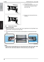
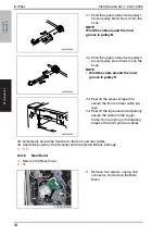
Remove two screws (to which no red paint has been applied). Then, remove the Scan-
ner Assy from the Scanner Drive Cables.
NOTE
• Removal of the Scanner Assy leaves the front and rear Scanner Drive Cables
attached with the fixing brackets.
3.
Remove one screw and the cable
holder.
4.
Remove one flat cable and the Scan-
ner Assy.
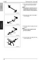
4035D077AA
4035D078AC
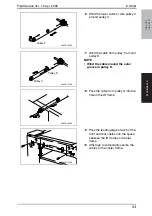
4035D079AA
4035D080AA


