background image

2 — ENG

TABLE OF CONTENTS

SAFETY GUIDELINES ................................................................................................................ Cover Page

WARRANTY STATEMENT ...............................................................................................................

 3

WARNING CHART .......................................................................................................................... 4-5

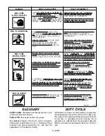
GLOSSARY ....................................................................................................................................

 5

DUTY CYCLE .................................................................................................................................

 5

DESCRIPTION OF OPERATION ......................................................................................................

 6

INSTALLATION AND BREAK-IN
PROCEDURES ............................................................................................................................... 6-7

Location of Air Compressor ................................................................................................ 6

Extension Cords ................................................................................................................. 6

Grounding Instructions ..................................................................................................... 6-7

Air Hose .............................................................................................................................. 7

OPERATING PROCEDURES ..........................................................................................................

7

STORAGE ....................................................................................................................................... 8

AIR COMPRESSOR
DIAGRAM ........................................................................................................................................ 9

TROUBLESHOOTING GUIDE .......................................................................................................... 10

HOW TO ORDER REPAIR PARTS ............................................................................................. Back Cover

Page

Summary of Contents for FA100

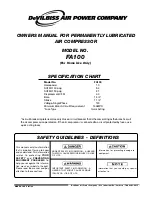
Page 1: ...ORMATION A HAZARD THAT MIGHT CAUSE SERIOUS INJURY OR LOSS OF LIFE Information that you should pay special attention to URGENT SAFETY INFORMATION A HAZARD THAT WILL CAUSE SERIOUS INJURY OR LOSS OF LIFE...

Page 2: ...GLOSSARY 5 DUTYCYCLE 5 DESCRIPTIONOFOPERATION 6 INSTALLATIONANDBREAK IN PROCEDURES 6 7 LocationofAirCompressor 6 ExtensionCords 6 GroundingInstructions 6 7 AirHose 7 OPERATINGPROCEDURES 7 STORAGE 8 AI...

Page 3: ...t Authorized Warranty Service Center that provides on site service calls for service call arrangement If the purchaser does not receive satisfactory results from the Authorized Warranty Service Center...

Page 4: ...FOOTBALLS BASKETBALLS ETC HOSE IS PERMANENTLY ATTACHED TO THE COMPRESSOR AND SHOULD ONLY BE REPLACED BY AUTHORIZED SERVICE CENTER PERSONNEL USING CERTIFIED REPLACEMENT PARTS ALWAYS OPERATE THE COMPRES...

Page 5: ...OSE YOU TO MOVING PARTS AND ELECTRICAL SHOCK A PORTABLE COMPRESSOR CAN FALL FROM A TABLE WORKBENCH OR ROOF CAUSING DAMAGE TO THE COMPRESSOR WHICH COULD EXPOSE YOU TO HAZARD OUS MOVING OR ELECTRICAL PA...

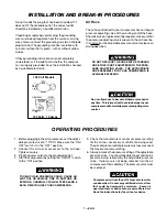
Page 6: ...Clean or blow off dust or dirt that collects on the air compressor A clean air compressor runs cooler and provideslongerservice Theventilationopeningsonyour aircompressorarenecessary tomaintainproper...

Page 7: ...t may contain water condensation Donotsprayunfilteredairatanitem that could be damaged by moisture Some air operated tools or devices may require filtered air Read the instructions for the air tool or...

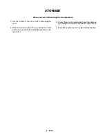
Page 8: ...o OFF and unplug the cord 2 Relieve all pressure from the air compressor head andairhosebysettingtheadjustablepressurevalve to 10 P S I 3 Protecttheelectricalcordandairhosefromdamage bywindingthemloos...

Page 9: ...OMPRESSOR DIAGRAM PARTS AVAILABLE FOR THIS UNIT DESCRIPTION PART NUMBER Pressure Valve Assembly CAC 4324 Connecting Rod Kit KK 4926 Fastener Kit KK 4929 Isolator Kit KK 4930 Pressure Valve Assembly ON...

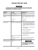
Page 10: ...be using a Quick Acting fuse 3 Check for low voltage problem 4 Check the extension cord 5 Disconnect the other electrical appliances from circuit or operate the compressor on its own branch circuit Fu...

Page 11: ...11 ENG SERVICE NOTES...

Page 12: ...horized Service Center always give the following information Model number of your product Part number and description of the item you wish to purchase WARRANTY This product is covered by the DeVilbiss...

Reviews: