background image

SB-2-226-B      Page 11

8.

Slide kink guard spring over end of
fluid tube. Spring should extend
approximately 3" into skeleton as
shown in illustration. Press spring
(requires a little force) into slot at
base of skeleton.

Figure 21

  9. Install left and right grips onto gun

using grip clips.

1 0 . Compress spring guard on opposite

end to expose nylon tube.

11. Slide spring retainer over tube

against spring.

12. Assemble fluid connector to tube.
13. Push spring retainer tightly over

fluid connector.

14. Push spring into opening of spring

retainer with a twisting action.
Insert a minimum of 1/2".

15. Install “S” clip to air hose and fluid

connector.

1 6 . Install spray head.

Air Fitting (42)

1.

Refer to gun grips procedure and
remove gun grips (38 and 39).

2.

Pull lower spring clip (44) from gun
body handle, and pull air fitting (42)
from gun handle.

3 .

Install end of air fitting (42) into gun
body handle.

4 .

Push on air fitting until you can see
daylight through lower spring clip
hole and install lower spring clip (44)
into gun body.

5.

Refer to gun grips procedure and
install gun grips (38 and 39).

Figure 16

Figure 17

Pneumatic Trigger Module (52)

1.

Refer to gun grip procedure and
remove gun grips (37) and (38).
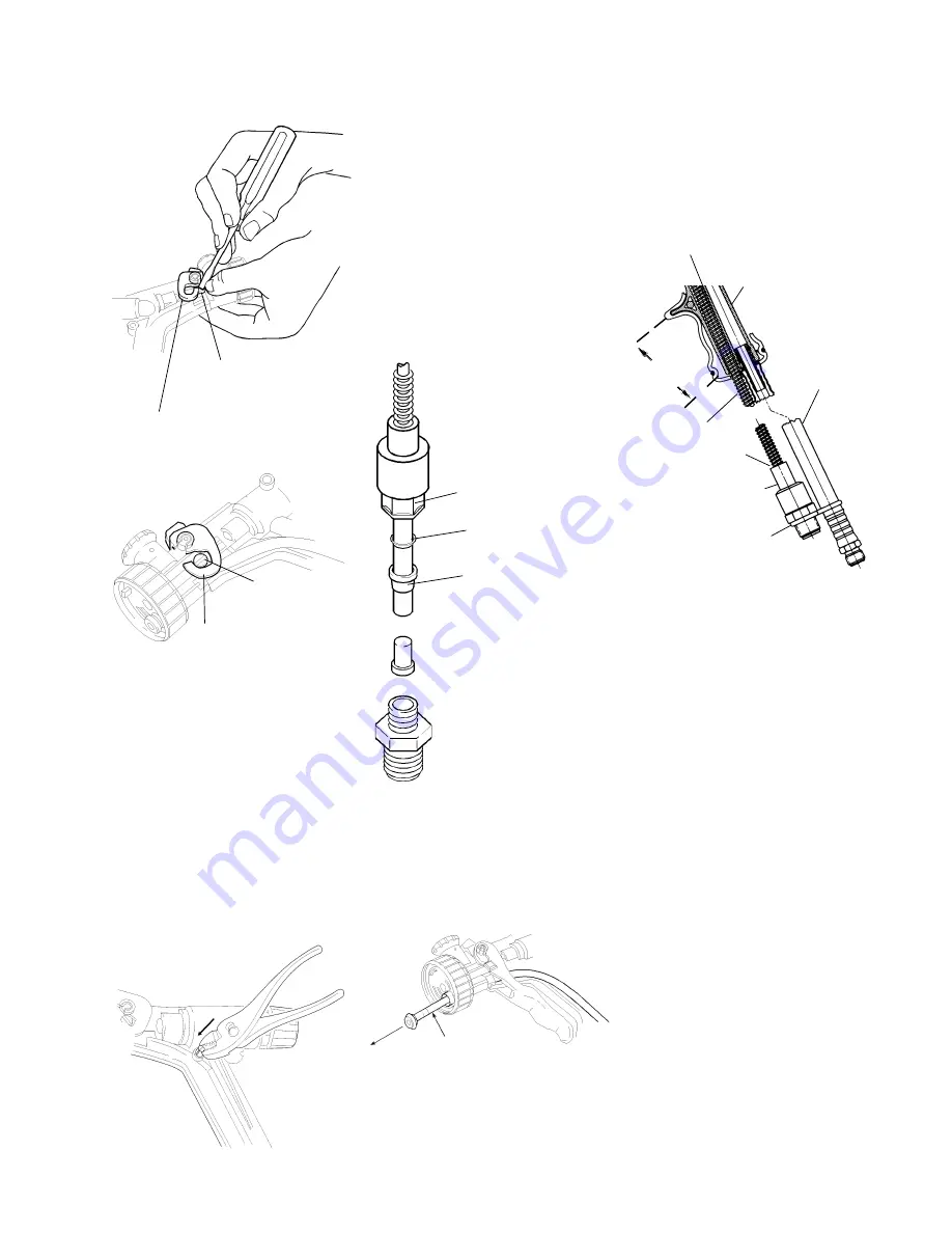
2.

To remove pneumatic trigger mod-
ule (52), squeeze the retaining barbs
with a pair of pliers and push to-
wards the skeleton (Figure 18). Pull
valve out of skeleton from the
opposite side.

3.

Install new pneumatic valve (52) by
locating valve body into skeleton,
then pushing until retaining barbs
engage on opposite side of skeleton.
Lube O-ring with SSL-10 gun lube
prior to assembly.

4.

Refer to gun grip procedure and in-
stall gun grips (37) and (38).

Figure 18

Fluid Tube and Spring Guard Assembly

1 .

Refer to gun grips procedure and re-
move gun grips (38 and 39).

2 .

Refer to fluid head and needle assem-
bly procedure and remove head and
needle.

3 .

Remove packing/spring (7).

4 .

Remove spring retainer and tube con-
nector (48) from fluid tube. Remove
connector nut, ferrule, ferrule
washer, and P-tube, Figure 19,
from fluid tube.

5.

Pull fluid tube through loops of
spring.

Figure 19

6 .

Pull fluid tube out from front of gun
body, Figure 20.

7 .

Install fluid tube assembly (47) into
round hole at bottom of gun
skeleton.

Figure 20

T-Block

Actuator

Arm

T-Block

Actuator

Arm

Ferrule Washer

Ferrule

P-Tube

Connector Nut

Connector

Note:

 Be sure to screw connector

nut completely onto connector un-
til it bottoms out. Also, be sure
tube is bottomed out into
connector.

Fluid Tube

Press spring

into skeleton.

Skeleton

Approx. 3"

Spring Guard

Push spring

tightly 

into retainer

Spring Retainer

Fluid

Connector

Air Hose

(Ref.)

Summary of Contents for MAX-504

Page 1: ...Thegun is intended for use with a pressure feed paintsupply The MAX 504 weighs only 12 ounces 340g Thehandlegripiscontouredtofit the palm The primary trigger requires less than 2 pounds 908 g of force to pull and the pneumatic trigger less than 1 pound 454 g SPECIFICATIONS Air Inlet 1 4 Fluid Inlet 3 8 Body Engineered Resins Wetted Parts EngineeredResins S S Weight 12 ounces 340 g Fluid Delivery P...

Page 2: ...alogenated hydrocarbon solvents for The MAX 504 HVLP Paint Spray Gun can be used with Incompatible example methylene chloride and 1 1 1 these solvents However aluminum is widely used in Materials h are not chemically compatible with the other spray application equipment such as material aluminum that might be used in many pumps cups and regulators valves etc Check all system components The chemica...

Page 3: ...s must be isolated and released The disposal of waste materials must be carried out in an approved manner Burning may generate toxic fumes The removal of waste solvents and coating materials should be carried out by an authorized local waste disposal service Cumulative Trauma Use of hand tools may cause cumulative Risk is reduced by avoiding or lessening factors 1 7 Disorders CTD s trauma disorder...

Page 4: ... is being used CLEANING Note Use normal cleaning procedures to clean the MAX 504 spray gun It should not be necessary to remove the spray head or fluid tube to clean the gun internally As with all spray guns soaking the gun is not recommended as this removes lubrication and can affect performance Disconnect the fluid supply hose at the fluid source and attach cleaning solvent hose A SolventSaver h...

Page 5: ...e may occur 5 Grasp fluid head 6 firmly and pull straight off from gun body If there is anydifficultyremoving applyaslight wiggling motion to free the fluid end from the fluid tube o ring 10 Note The fluid head 6 and needle 12 should be replaced as a set If replacing the fluid head and needle be sure to also replace the packing 8 to prevent fluid leakage 6 Remove packing spring 7 7 Remove fluid tu...

Page 6: ... needle in completely Install needle spring 13 and screw in fluid control knob 35 Turn knob com pletely in clockwise then back out 1 1 2 to 2 turns for full fluid flow Figure 8 25 Apply SSL 10 gun lube to the air cap threads Screw the air cap assembly 1 onto the fluid head 6 Tighten hand tight do not overtighten 26 Refer to gun grip procedure and install gun grips 38 and 39 4 Using a 1 1 16 inch 2...

Page 7: ...SB 2 226 B Page 7 7 8 9 10 46 24 25 11 13 30 29 28 33 31 20 44 Figure 9 KK 5054 Repair Kit 36A 34 19 18 17 26 36A ...

Page 8: ...26 B Figure 10 MAX 504 Spray Gun Exploded View 14 8 10 46 11 9 7 15 16 2 3 4 6 1 19 18 20 17 22 23 27 50 38 36 47 10 46 48 49 45 43 44 51 41 37 40 36 33 31 35 34 32 12 30 29 28 24 25 13 5 21 21 36A 5 42 26 52 36A 39 ...

Page 9: ... Description 1 OMX 411 46MP Air Cap Kit OMX 411 83MP Air Cap KIt 2 OMX 11 Air Cap retaining ring air cap retaining nut 3 Air Cap 46MP 4 OMX 45 K2 Seal Kit Kit of 2 5 OMX 4033 Fluid Head and Needle Kit 055 1 4 mm 65 10 head OMX 4034 Fluid Head and Needle Kit 042 1 1 mm 65 10 head OMX 4035 Fluid Head and Needle Kit 070 1 8 mm 65 10 head OMX 4036 Fluid Head and Needle Kit 042 1 1 mm 50 10 head OMX 40...

Page 10: ... pencil or similar tool pry the actuator back off the skeleton mounting posts as shown Horn Air Control Knob 18 1 Refer to gun grips procedure and remove gun grips 38 and 39 2 Position gun body so that it is supported near the horn air spring pin 20 Use the pin removal tool 51 supplied with OMX 460 kit and a small hammer to drive out spring pin 20 3 Pull horn air valve 18 from gun body If cleaning...

Page 11: ...and 38 2 To remove pneumatic trigger mod ule 52 squeeze the retaining barbs with a pair of pliers and push to wards the skeleton Figure 18 Pull valve out of skeleton from the opposite side 3 Install new pneumatic valve 52 by locating valve body into skeleton then pushing until retaining barbs engage on opposite side of skeleton Lube O ring with SSL 10 gun lube prior to assembly 4 Refer to gun grip...

Page 12: ...ng 1 Cut the old head retaining ring 15 using wire cutter and remove from the gun body 2 Remove and discard the retaining ring clip 16 3 Position the new retaining ring clip over the retaining ring groove in the head end of the skeleton Figure 23 4 Close the clip with one hand then push the retaining ring back until it slides over the clip and snaps in place When properly secured the head retainin...

Page 13: ...ced fluid flow pressure turning fluid control knob counterclockwise or increase fluid pressure on pressure feed container Excessive horn fan air Reduce horn air E Jerky or fluttering spray Loose air cap Tighten retaining ring Obstructed fluid passage or tube Clean Loose or cracked fluid tube in cup or tank Tighten or replace Insufficient fluid in cup or pressure tank Fill cup or tank F Improper sp...

Page 14: ...n clockwise fluid flow Note air leaks through opening in knob Excessive air leak in rear of gun behind Identify cause and correct piston Orifice in piston U Cup obstructed Clean orifice in U Cup Seal face of bushing and or piston U Cup Replace M Slow sluggish needle Partial obstruction in orifice of piston U Cup Clean Orifice return when trigger released pneumatic Excessive air leak in rear of gun...

Page 15: ...HOSE OF MERCHANTABILITY AND FITNESS FOR A PARTICULAR PURPOSE ARE LIMITED TO 24 MONTHS FROM PURCHASE AND TO THE EXTENT PERMITTED BY LAW ANY AND ALL IMPLIED WARRANTIES ARE EXCLUDED THIS IS THE EXCLUSIVE REMEDY AND LIABILITY FOR CONSEQUENTIAL AND INCIDENTAL DAMAGES UNDER ANY AND ALL WARRANTIES IS EXCLUDED TO THE EXTENT EXCLUSION IS PERMITTED BY LAW SOME STATES DO NOT ALLOW LIMITATIONS ON HOW LONG AN ...

Page 16: ...48 48 each Disposable Spray Gun Covers Save money by reduc ing cleaning time and maintenance with these covers that also limit operator expo sure to overspray HD 503 SolventSaver Hose Gun Cleaner QMGZ SolventSaver Hose Gun Cleaner Spray Gun Lube SSL 10 2 oz bottle Compatible with all paint materials con tains no silicone or pe troleum distillates to contaminate paint MSDS available upon request 2 ...

Reviews: