Page 6 SB-2-226-B
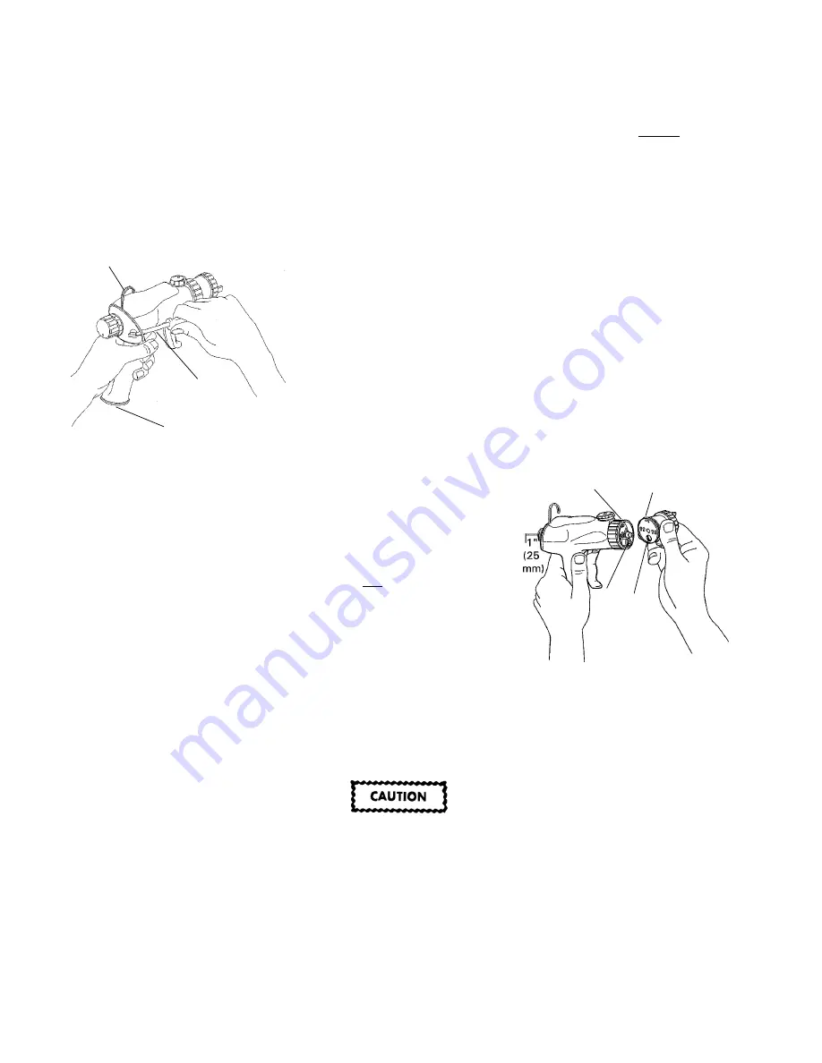
Gun Grips (38 and 39)
1 .
Place 1/4" (6 mm) flat blade screw-
driver, Figure 7, and pry upper clip
out of groove. Expand the bottom
of the clip to remove from the
mounting slots.
2.
To remove the lower clip (41) from
the gun grips, use a pair of external
retaining pliers or push down on the
clip tabs with your thumbs.
3 .
Separate grips at handle and top by
prying christmas tree clips (37).
4.
Pull outward on the back of each
grip to disengage the grips from the
notch at the front of the body under
the fluid head retaining ring (15).
5.
To reassembly grips, install right gun
grip. Push grip down into position.
6 .
Install tab on left gun grip (38) into
slot under retaining ring and push
grip down into position.
7.
Push grips together at christmas
tree clips (37).
8.
Install lower clip (41) and upper clip
(40).
Air Valve Bushing (29), Seal (28), Piston
(30), and Air Seal (33) (Parts included in
Gun Repair Kit KK-5054)
Note
It is recommended that you use
the gun repair kit KK-5054, Fig-
ure 9, when undertaking this pro-
cedure. Use all parts provided in
the kit. Refer to the various pro-
cedures in this manual to access
all kit parts.
1 .
Refer to gun grips procedure and
remove gun grips (38 and 39, Figure
10).
2.
Refer to fluid head and needle
assembly procedure and remove
head and needle assembly.
3.
Remove packing/spring (7), fluid
tube o-ring (10), and baffle seal (11).
16. Install baffle seal (11) into face of
spray gun body.
17. Install o-ring (10) onto fluid tube (47).
Lubricate o-ring with SSL-10 gun lube.
1 8 . Install needle (12) partially into gun
body through rear opening, Figure 8.
Leave about 1" of needle exposed
out rear of gun.
19. Apply two drops of gun lube to fluid
head (6) threads. (Lubrication facili-
tates removal of parts after use.)
20. Place packing/spring (7) on the end
of the needle.
21. Place fluid head against gun body,
ensuring fluid head lines up with fluid
tube opening, Figure 8. Firmly push
fluid head over fluid tube o-ring
and against head retaining ring.
22. Turn head retaining ring (15) coun-
terclockwise to draw fluid head
onto body. Hand tighten head retain-
ing ring until fluid head is drawn
firmly against the gun body.
23. Push needle in completely. Install
needle spring (13) and screw in fluid
control knob (35). Turn knob com-
pletely in clockwise, then back out
1-1/2 to 2 turns for full fluid flow.
Figure 8
25. Apply SSL-10 gun lube to the air cap
threads. Screw the air cap assembly
(1) onto the fluid head (6). Tighten
hand tight, do not overtighten.
26. Refer to gun grip procedure and
install gun grips (38 and 39).
4.
Using a 1-1/16 inch (27 mm) socket
or adjustable wrench, unscrew rear
plug (34) from gun body.
5.
Remove piston return spring (31).
Using your finger, push air seal (33)
out of rear plug (34).
6.
Remove piston assembly (30). You
can either remove the piston by
striking the back of the gun body
against the palm of your hand or by
pulling it out with a pair of needle
nose pliers.
7 .
Remove air valve bushing (29) and
seal (28). To remove, use a dental
pick to catch the center hole, and
pull out.
8.
(OPTIONAL) Pull out air inlet retainer
(24) and remove air inlet plug (25)
with o-ring (26).
9 .
Pull out lower spring clip (44) and
remove air fitting (42). Remove
o-rings (43) from fitting.
Note
When assembling spray gun,
lube all sliding parts with pure
petroleum jelly (petroleum based
grease).
10. Install o-rings (43) into fitting (42), the
lower groove is for lower spring clip.
Lubricate o-rings (43) and slide fitting
into skeleton.
1 1 . Push on fitting until you can see light
through the lower spring clip hole
and install lower spring clip (44) into
skeleton. Install spring clip into gun
body form the left hand side.
12. Apply a thin film of pure petroleum
jelly (petroleum based grease) to in-
side diameter of the skeleton (50) and
outer surface of piston shaft (30).
Install piston assembly (30) into air
valve bushing (29). Slide u-cup seal
(28), grooved end towards bushing,
onto piston shaft.
1 3 . Install assembled air valve bushing
and piston into gun body. Push in
completely.
1 4 . Install air seal (33, Figure 8), tapered
end first, into rear plug (34). Install
spring (31) into plug.
Overtightening can damage the
plug or gun skeleton. When
tightening rear plug into gun
body do not overtighten. Snug
only.
15. Push assembled rear plug into back
of gun body and thread into gun. Use
a 1-1/6 inch (27 mm) socket or cres-
cent wrench to snug rear plug into
gun body, do not overtighten.
Figure 7
Flat Blade
Screwdriver
Upper Clip
Lower Clip
Fluid Head
Head Retaining
Ring
Fluid
Tube
Fluid
Tube
Opening


