background image

8

ASSEMBLY INSTRUCTIONS

Installing Handle, Foot Extension
Bracket, Wheels, Outlet Valve

THE WHEELS AND HANDLE DO NOT PRO-
VIDE ADEQUATE CLEARANCE, STABILITY
OR SUPPORT FOR PULLING THE UNIT UP
AND DOWN STAIRS OR STEPS. THE UNIT
MUST BE LIFTED OR PUSHED UP A RAMP.

Do not use the engine gas tank as a support
for lifting the air compressor.

1.

Insert the handle into pockets under the tank
saddle. Put one set screw through hole in one side
of tank saddle and tighten down on handle.

It may be necessary to brace or support one
end of the outfit when attaching the wheels
and the foot extension bracket because the
air compressor will have a tendency to tip
before both wheels are assembled.

Items Needed for Assembly

20 oz. of oil for the engine (see Briggs & Stratton
instructions). Use 10W30 high quality motor oil.

16 oz. of compressor oil, SAE 20-20W, non-deter-
gent, low foaming.

a 9/16" socket or open-end wrench for attaching the
wheels.

a 7/16" open-end wrench for attaching the foot
extension bracket and rubber feet.

a 1/4" open-end wrench to tighten handle set
screw.

an adjustable wrench for attaching the shut-off
valve and air outlet adapter.

EXCESSIVE TANK VIBRATION CAN WEAK-
EN THE AIR TANK AND CAUSE RUPTURE
OR EXPLOSION. RUBBER FEET MUST BE
INSTALLED.

2.

Attach the rubber feet to the bottom of the foot
extension bracket. Attach foot extension bracket to
the air tank bracket. Use one cap screw, one lock
washer, and one hex nut at each end. Tighten.

3.

The leg bracket on the underside of the air com-
pressor tank has 2 holes on each side for mounting
the wheels. Place one shoulder bolt through the
hole in a wheel. Next, push the bolt through the

LOWER

 hole of the leg bracket and screw on one

hex locking nut. The special locking nut does not
turn freely. Tighten the nut firmly until it contacts the
tank leg. See separate Parts Manual. The outfit will
sit level if the wheels are properly installed.

4.

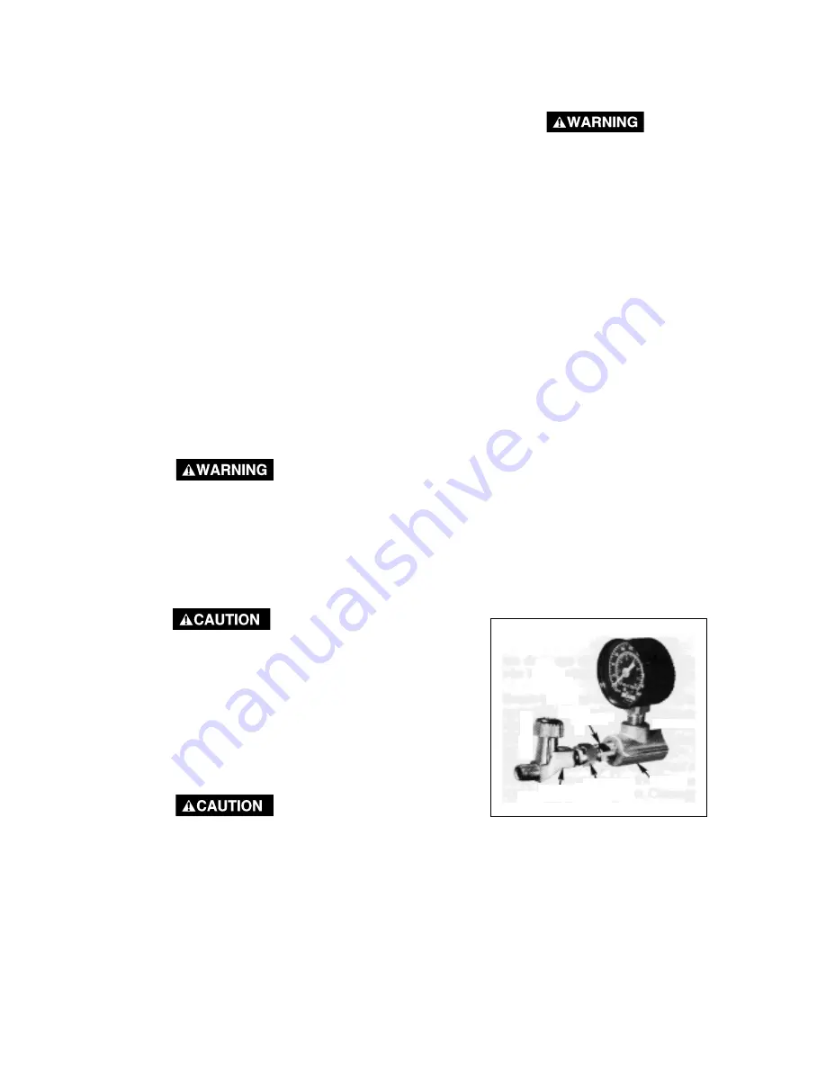
Apply teflon tape to the tapered pipe threads on the
adapter and tighten into the manifold. Install the
swivel connection end of the shut-off valve to the
straight threaded end of the adapter (teflon tape is
not required) and tighten this connection. See photo
below.

5.

Attach the spark plug wire to the spark plug.

ADAPTER

SHUT-OFF

VALVE

MANIFOLD

SWIVEL

CONNECTION

Summary of Contents for MG4-OLENG-2B

Page 1: ...cultural crops forest brush grass or other similar items then an approved spark arrester must be installed and is legally required in the state of California It is a violation of California statutes s...

Page 2: ...Back Cover SAFETY GUIDELINES DEFINITIONS This manual contains information that is important for youtoknowandunderstand Thisinformationrelatesto protecting YOURSAFETY and PREVENTINGEQUIP MENT PROBLEMS...

Page 3: ...ation and start up cost o ANYINCIDENTAL INDIRECTORCONSEQUENTIALLOSS DAMAGE OR EXPENSETHATMAYRESULT FROM ANY DEFECT FAILURE OR MALFUNCTION OF THE PRODUCT Some states do not allow the exclusionorlimitat...

Page 4: ...D FUEL OUTDOORS OR IN A WELL VENTILATED AREA MAKE SURE THERE ARE NO SOURCES OF IGNITION SUCH AS CIGARETTES NEAR REFUELING LOCATION OPERATE COMPRESSOR IN AN OPEN AREA AWAY FROM DRY BRUSH WEEDS OR OTHER...

Page 5: ...PREVENT IT ALWAYS WEAR ANSI Z87 1 APPROVED SAFETY GLASSES WITH SIDE SHIELDS WHEN USING THE COMPRESSOR NEVER POINT ANY NOZZLE OR SPRAYER TOWARD ANY PART OF THE BODY OR AT OTHER PEOPLE OR ANIMALS ALWAY...

Page 6: ...ds of the ASME CFM Cubic feet per minute CaliforniaCode UnitmaycomplywithCaliforniaCode 462 L 2 M 2 Specification model label is on the side of the tank on units that comply with California Code Unloa...

Page 7: ...ff Valve Turn the knob counterclockwise to open the valve and clockwise to close Air Compressor Pump To compress air the piston moves up and down in the cylinder On the down stroke airisdrawninthrough...

Page 8: ...tighten handle set screw an adjustable wrench for attaching the shut off valve and air outlet adapter EXCESSIVETANKVIBRATIONCANWEAK EN THE AIR TANK AND CAUSE RUPTURE OR EXPLOSION RUBBER FEET MUST BE I...

Page 9: ...uctions that could interfere with the flow of air through the fan bladed flywheel The air compressor crankcase and head are designed with fins to provide propercooling If humidity is high an air filte...

Page 10: ...EAS DO NOT REFUEL OR CHECK GASO LINE LEVEL WHILE THE ENGINE IS RUN NING DO NOT STORE SPILL OR USE GASOLINE NEAR AN OPEN FLAME Break in Procedures 1 Open outlet valve to prevent pressure from build ing...

Page 11: ...artthecompressoroutfitandcheckthefollowing 1 Before attaching an air hose or accessory make sure the engine is off Close the outlet valve or pressure regulator If an optional air pressure regulator is...

Page 12: ...ance schedule is geared to an outfit in a normal working environmentoperatingonadailybasis Ifnecessary thescheduleshouldbemodifiedtosuittheconditionsunderwhich your compressor is used The modification...

Page 13: ...E DOES NOT WORK PROPERLYOVER PRESSURIZATIONCAN OCCUR AND CAUSE AIR TANK RUPTURE OR EXPLOSION DAILY PULL THE RING ONTHESAFETYVALVEANDMAKESUREIT OPERATESFREELY IFTHEVALVEISSTUCK OR DOES NOT OPERATE SMOO...

Page 14: ...levelbylooseningthetwojamnutsonthe throttle control cylinder readjusting its position and retighteningthenuts SeeFigure6 Properidlespeedis between 2400 and 2600 RPM If the throttle mechanism fails to...

Page 15: ...ding pages and per form maintenance as necessary Drain the water from the air tank 2 ReviewtheBriggs Stratton OperatingandMain tenanceInstructions 3 Remove the air tool or accessory 4 Protect the air...

Page 16: ...into the cylinder Reas sembleusingnewgasketsandtorquescrews25 to 30 ft lbs Check both nuts and tighten if required PERFORMING TROUBLESHOOTING OR REPAIRS CAN EXPOSE MOVING PARTS OR COMPRESSED AIRSOURCE...

Page 17: ...ling sound Loose belt There is no oil in the compressor Adjust belt tension per instructions under Engine Adjustments section of this manual Add oil to top of fill hole in base 16 oz capacity Engine w...

Page 18: ...18 SERVICE NOTES...

Page 19: ...19 SERVICE NOTES...

Page 20: ...Manual or is available upon request Call our Toll Free Number 1 800 888 2468 Ext 2 then Ext 1 to obtain the location of the nearest Authorized Service Center for ordering repair parts and for warranty...

Reviews: