background image

PAGE  4        Sb-19-085-P

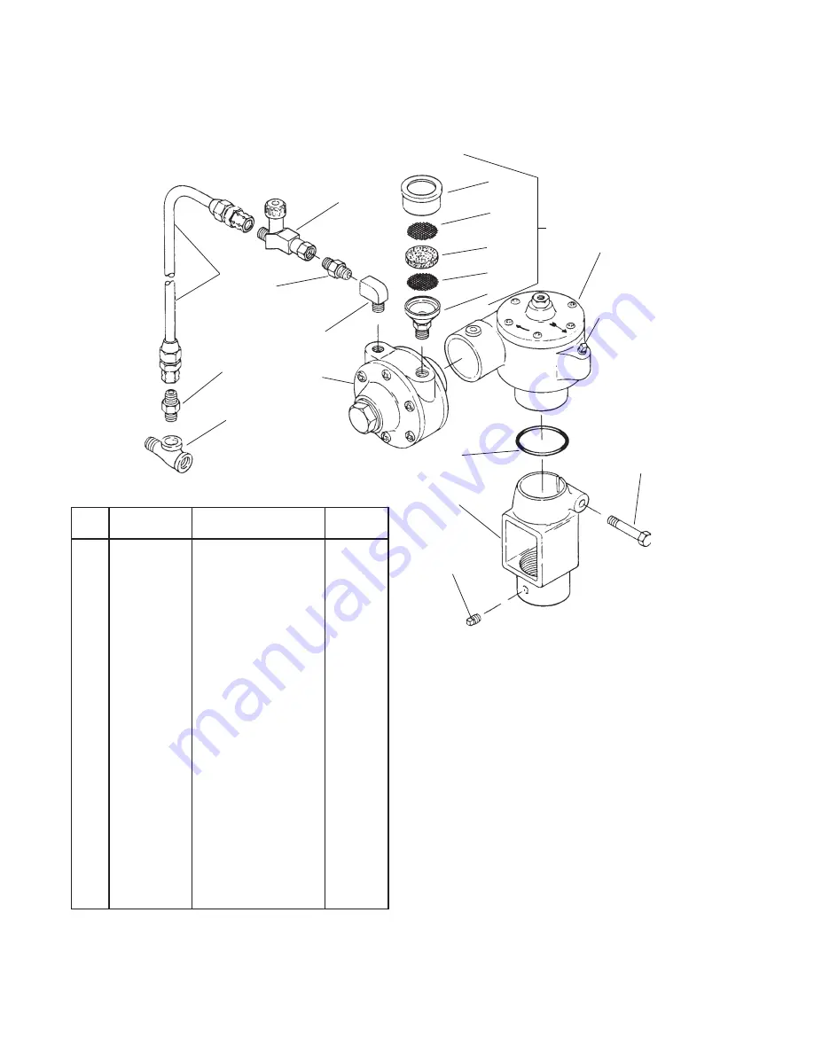
FIGURE 1   GEAR DRIVE AIR MOTOR

QS-5001 (STANDARD DUTY)

Oil

Fill

16

See Figure 3

for Gear box

Assembly

7

10

9

8

8

6

4

3

5

2

11

13

12

15

See

Figure 2

for Air

Motor.

14

1

  Ref  Replacement   

Ind. Parts

  No.  Part No. 

Description 

 Req'd.


--- 

Service Tee 1/4" 

1


  Galvanized


  Purchase Locally


H-2008  

Nipple 1/4" NPS(M) 2


  x 1/4" NPT (M)


HA-5863 

Hose Assembly 1-1/2 ft. 

1

 4  HAV-500 

Air Adjusting Valve 1


  1/4" NPS(M) x 


  1/4" NPS(F) 


--- 

Street Elbow  

1


  1/4"(M) x 1/4"(F)NPT


  Purchase Locally


350-401 

Air Strainer Assembly 

1


--- 

Strainer Cap 

1

 *8  --- 

Screen 

 *

9 --- 

Felt 

1

  10 

--- 

Strainer body 

1

 11  32243-133 

Washer 

1

 12  QS-70-2 

Support 

1

  13 


Hex Head Cap


  Screw 3/8"-16 x 2" 

1


  Purchase Locally

  14 

--- 

Square Head Set 


  Screw 1/4-20 x 3/8"


  Purchase Locally

  15 

--- 

Air Motor (Figure 2) 

  REF

  16 

--- 

Gear box (Figure 3) 

  REF

 Included in KK-5001-1 Air Motor Repair Kit (See Pg. 5 

for  

  additional items provided in kit.)

*Ref. No. (8) 2 ea. and Ref. No. (9) 4 ea. included in KK-5006 

  Strainer Screen and Felt Kit.

2

Summary of Contents for QS-5001

Page 1: ...ator shaft Tighten cap screw 13 3 For single regulation proceed as fol lows a Removeairinletvalvefrom regula tor on tank and install service tee 1 in regulator b Reinstall air inlet valve in service t...

Page 2: ...zard Halogenated hydrocarbon solvents Aluminum is widely used in spray application Incompatible Materials for example methylene chloride and equipment such as material pumps cups 1 1 1 Trichloroethane...

Page 3: ...e rigidly supporting the opposite drive end of the shaft Gear Box Refer to Figure 3 1 Remove oilfill plug 37 orcoverplate 33 and drain gear box lubricant 2 Remove set screws 40 and gear box 16 Figure...

Page 4: ...V 500 Air Adjusting Valve 1 1 4 NPS M x 1 4 NPS F 5 Street Elbow 1 1 4 M x 1 4 F NPT Purchase Locally 6 350 401 Air Strainer Assembly 1 7 Strainer Cap 1 8 Screen 2 9 Felt 1 10 Strainer Body 1 11 32243...

Page 5: ...Screw 12 1 4 28 x 1 2 20 QS 334 End Plate 1 21 QS 189 1 K10 Dowel Pin 4 Kit of 10 22 PT 59 K10 End Plate Gasket 2 Kit Kit of 10 23 Vane 4 24 QS 442 Rotor and Shaft 1 25 QS 335 Body 1 26 QS 333 Front P...

Page 6: ...6 Gasket 1 37 Pipe Plug 1 4 1 Galvanized Purchase Locally 38 QS 36 1 Housing 1 39 Oil Seal 1 40 Cup Point Set Screw 2 5 16 18 x 3 8 41 Gasket 1 42 QS 59 Worm Gear 1 43 Spacer 1 44 Key No 5 5 8 x 1 8 1...

Page 7: ...embly 36 and or worm gear 43 worn Figure 3 5 Air motor bearing 19 or 29 worn Figure 2 1 Disassemble and clean per parts replacement instruc tions 2 Disassemble clean motor per parts replacement instru...

Page 8: ...ised Figure 2 Repair Kit PT 77 K10 End Plate PT 59 K10 End Plate Gasket Kit Directly O Ring 7 11 2011 DeVilbiss All rights reserved Printed in U S A U S A Canada Customer Service 195 Internationale Bl...

Reviews: