9. Features
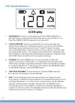
9.1) Defined Features
1.
LCD SCREEN:
Indicates the pump operating pressure and displays
symbols (also features a blue backlight).
2.
CONNECTION TUBING:
Tubing which connects canister to drainage
tubing.
3.
BATTERY POWER:
Indicates how much battery power is left. Icon has 1-4
bars representing 25%, 50%, 75%, and 100% battery power.
4.
CANISTER CLIP:
Clip that connects the canister to the NPWT device.
5.
MODE SYMBOL:
Indicates pump operating mode (continuous or
intermittent).
6.
MODE BUTTON:
Allows user to set the pump to either continuous or
intermittent mode.
7.
POWER PLUG:
Enables user to charge device.
8.
PUMP BUTTON:
Used to turn pump on or off. Also can be used to
exit a setting.
9.
SET BUTTON:
Used to program desired pressure.
10.
POWER SWITCH:
Used to turn the system power on and off.
3.) Battery Power
1.) LCD Screen
9.) SET Button
6.) Mode Button
8.) Pump Button
7.) Power Plug
4.) Canister Clip
5.) Mode Symbol
10.) Power Switch
2.) Connection Tubing
9
10


