


8
OPERATION
Switch
WARNING:
Hold the tool firmly with both hands to maintain control upon start up
and during use and until the wheel or accessory stops rotaing. Make sure the wheel
has come to a complete stop be fore setting the tool down.
1
0
E
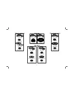
To turn the tool on, lift up the toggle switch button (E)
to the 1 position. Turn off the tool by pushing the toggle
switch button (E) to the 0 position.
NOTE:
Allow the tool to reach full speed before touching
tool to work surface. Lift the tool from the work surface
before turning the tool off.
Spindle Lock
WARNING:
Never depress the spindle lock button while the grinder is running.
Never turn the grinder on while the spindle lock button is depressed. ALWAYS wait
until the tool has come to a complete stop before engaging the spindle lock. Damage
to your tool or personal injury may result.
The spindle lock (A) is provided to prevent the spindle from rotating when installing
or removing wheels.
To engage the spindle lock, press the spindle lock button (A) and rotate the spindle
until you are unable to rotate it further.
Guards and Flanges
It is important to choose the correct guards and flanges to use with the grinder
accessories. See page 9 for correct accessories.
NOTE:
Edge grinding and cutting may be performed with Type 27 wheels designed
and specified for this purpose.
WARNING:
100 mm abrasive wheels with rated max. speed lower than
13500RPM can’t be used on this grinder. Accessories must be rated for at least the
speed recommended on the tool warning label. Wheels and other accessories
running over rated accessory speed may burst and cause injury. Threaded
accessories must have a M10 hub. Every unthreaded accessory must have a 16 mm
arbor hole. If it does not, it may have been designed for a circular saw and should
not be used. Use only the accessories shown on manual. Accessory ratings must be
above listed minimum wheel speed as shown on tool nameplate.
Mounting and Using Depressed Center Grinding Wheels and
Sanding Flap Discs
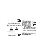
MOUNTING AND REMOVING HUBBED WHEELS
WARNING: To reduce the risk of serious personal injury, turn off and disconnect
tool be fore making any adjustments or removing or in stall ing ac ces sories.
Before
reconnecting the tool, turn the switch on and off to ensure that the tool is off.
Hubbed wheels install directly on the M10 threaded spindle. Thread of the accessory
must match the thread of the spindle.
1. Remove backing flange by pulling flange away from the machine.
2. Thread the wheel on the spindle by hand.
3. Depress the spindle lock button (A) and use a wrench to tighten the hub of the
wheel.
Reverse the above procedure to remove the wheel.
NOTICE:
Failure to properly seat the wheel against the spindle shoulder before turning
the tool on may result in damage to the tool or the wheel.
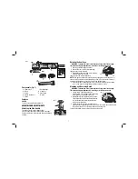
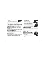
MOUNTING NON-HUBBED WHEELS
F
K
WARNING: To reduce the risk of serious personal
injury, turn off and disconnect tool be fore making any
adjustments or removing or in stall ing ac ces sories.
Before reconnecting the tool, turn the switch on and off to
ensure that the tool is off.
Depressed center, Type 27 grinding wheels must be used with flanges supplied on
product. See the chart on page 9 of this manual for more information.
1. Install the unthreaded backing flange (F) on spindle (K) with the raised section
(pilot) against the wheel. Be sure the backing flange recess is seated onto the
flats of the spindle by pushing and twisting the flange before placing wheel.
2. Place wheel against the backing flange, centering the wheel on the raised section
(pilot) of the backing flange.
Summary of Contents for D28000-XE
Page 1: ...D28000 XE Heavy Duty Small Angle Grinder INSTRUCTION MANUAL ...
Page 2: ......
Page 17: ...15 ...
Page 18: ...16 ...
Page 19: ...17 ...


