8
SPINDLE LOCK
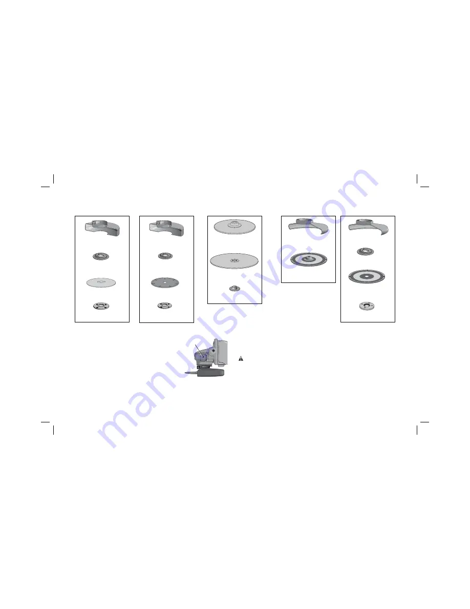
The spindle lock (C) is provided to prevent the spindle
C
from rotating when installing or removing wheels.
Operate the spindle lock only when the tool is turned off,
unplugged from the power supply, and has come to a
complete stop. Do not engage the spindle lock while the
tool is operating because damage to the tool will result.
To engage the lock, depress the spindle lock button and
rotate the spindle until you are unable to rotate the
spindle further.
Mounting and Using Depressed Center Grinding Wheels and
Sanding Flap Discs
MOUNTING AND REMOVING HUBBED WHEELS
WARNING: Turn off and unplug the tool before making any adjustments or
removing or installing attachments or accessories.
Before reconnecting the tool,
depress and release the paddle switch to ensure that the tool is off.
Hubbed wheels install directly on the 14M2 threaded spindle. Thread of accessory
must match thread of spindle.
1. Backing flange is retained to the grinder by an O-ring on the spindle. Remove
backing flange by pulling and twisting flange away form the machine.
2. Thread the wheel on the spindle by hand.
Type 1 guard
backing flange
abrasive cutting wheel
clamp nut
Cutting Wheels
Type 27 guard
hubbed sanding
flap disc
Type 1 guard
backing flange
diamond cutting wheel
clamp nut
Sanding Discs
rubber backing pad
sanding disc
threaded clamp nut
Sanding Flap Discs
Type 27 guard
backing flange
non-hubbed
sanding flap disc
threaded clamp nut
Summary of Contents for D28106-XE
Page 2: ......


