3
• Choice of triggering method is important.
Check
the manual for triggering options.
BUMP ACTION TRIGGER
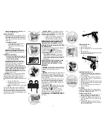
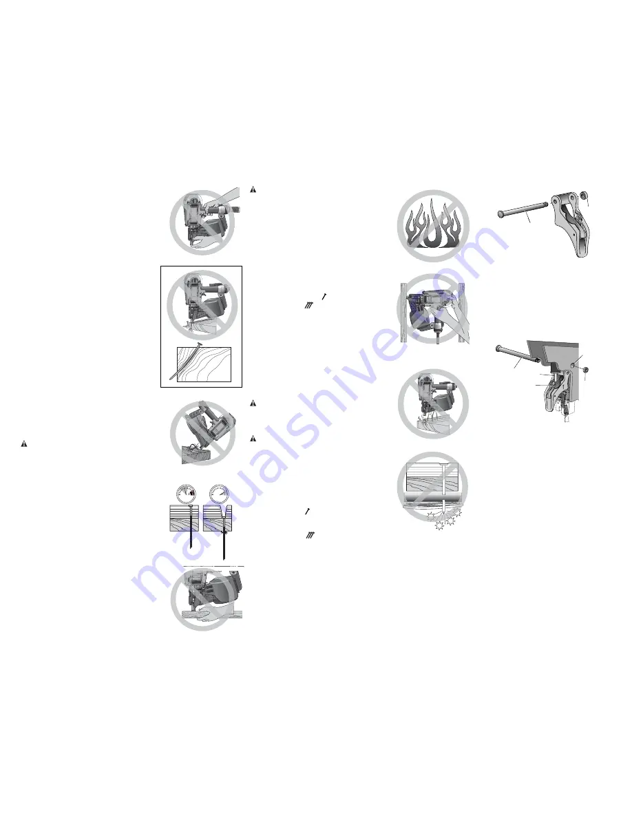
• When using the bump action trigger, be careful of
unin tentional double fires resulting from tool recoil.
Unwanted fasteners may be driven if the contact
trip is allowed to accidentally re-contact the work
surface. (Fig. T)
TO AVOID DOUBLE FIRES:
• Do not engage the tool against the work
surface with a strong force.
• Allow the tool to recoil fully after each
actuation.
• Use sequential action trigger.
• When “bump” actuating the framing nailer,
always keep tool in control.
Inaccurate placement
of tool can result in misdirected discharge of a
fastener.
SEQUENTIAL ACTION TRIGGER
• When using the sequential action trigger, do
not actuate the tool unless the tool is placed
firmly against the workpiece.
• Do not drive nails blindly into walls, floors
or other work areas.
Fasteners driven into live
electrical wires, plumbing, or other types of
obstructions can result in injury. (Fig. U)
• Stay alert, watch what you are doing and use
common sense when operating a power tool. Do
not use tool while tired or under the influence
of drugs, alcohol, or medication.
A moment of
inattention while operating power tools may result
in serious personal injury.
WARNING:
Some dust created by power sanding,
sawing, grinding, drilling, and other construction
activities contains chemicals known to the State of
California to cause cancer, birth defects or other
reproductive harm. Some examples of these chemicals
are:
• lead from lead-based paints,
• crystalline silica from bricks and cement and
other masonry products, and
• arsenic and chromium from chemically-treated
lumber.
Your risk from these exposures varies, depending on
how often you do this type of work. To reduce your
exposure to these chemicals: work in a well ventilated
area, and work with approved safety equipment, such
as those dust masks that are specially designed to filter
out microscopic particles.
WARNING: ALWAYS
use safety glasses. Everyday
eyeglasses are NOT safety glasses. Also use face or
dust mask if cutting operation is dusty. ALWAYS WEAR
CERTIFIED SAFETY EQUIPMENT:
• ANSI Z87.1 eye protection (CAN/CSA Z94.3),
• ANSI S12.6 (S3.19) hearing protection,
• NIOSH/OSHA/MSHA respiratory protection.
BEFORE OPERATING THIS TOOL, CAREFULLY READ
AND UNDERSTAND ALL INSTRUCTIONS IN THE
“IMPORTANT SAFETY INSTRUCTIONS” SECTION.
Additional Safety Instructions For Australia
And New Zealand
For Australia and New Zealand, nailers are supplied with
full sequential action trigger ( gray) only
.
The bump fire trigger (
black) is available as an
optional only for use in industry requiring bump fire
(e.g. pallet manufacture).
•
Young children and the infirm.
This appliance is
not intended for use by young children or infirm
persons without supervision. Young children should
be supervised to ensure that they do not play with
this appliance.
BEFORE OPERATING THIS TOOL, CAREFULLY READ
AND UNDERSTAND ALL INSTRUCTIONS IN THE
“IMPORTANT SAFETY INSTRUCTIONS” SECTION.
ASSEMBLY
WARNING:
Lock off trigger, disconnect air line from
tool and remove fasteners from magazine before making
adjustments or personal injury may result.
Trigger
WARNING:
Keep fingers AWAY from trigger when not
driving fasteners to avoid accidental firing. Never carry
tool with finger on trigger. In “Contact Bump Actuation
Mode” tool will fire a fastener if safety is bumped while
trigger is depressed.
In accordance with the ANSI Standard SNT-101-2002,
the D
E
WALT Nailers are assembled with a sequential
action trigger. For a replacement trigger contact your
authorized service center or call (AUS) 1800 654 155
or (NZ) 0800 339258.
The
gray trigger
with imprinted on the side, (Cat.#
D510023 kit) is the single sequential action trigger and
causes the tool to operate in this mode.
The
black trigger
with
imprinted on the side,
(Cat.# D510020 kit) is the bump action trigger and
permits the tool to be actuated in this manner.
For defining the use of the
sequential action trigger
and
bump action trigger
, see the
Actuating Tool
section of
this manual.
A
B
FIG. 1
TRIGGER REMOVAL (FIG. 1)
1. Lock off trigger.
2. Remove air from the tool.
3. Remove rubber grommet (A) from end of dowel pin
(B).
4. Remove dowel pin.
5. Remove trigger assembly from trigger cavity under
the handle of the tool housing.
E
D
B
C
FIG. 2
A
TRIGGER INSTALLATION (FIG. 2)
1. Select either the sequential or bump trigger to be
installed on the tool. Both triggers are included in
the tool packaging.
2. Insert the trigger subassembly into trigger cavity.
3. Ensure that trigger spring (C) is placed around the
trigger valve stem (D).
4. Align the holes of the trigger with the housing holes
(E), then insert the dowel pin (B) through the entire
assembly as shown.
5. Push the rubber grommet (A) onto the end of the
dowel pin as shown.
Air Fitting
The D
E
WALT framing nailers have a standard 3/8" pipe
thread for the air fitting. The tool is assembled with a 3/8"
to 1/4" adapter installed in the end cap.
TO INSTALL AN AIR FITTING
1. Wrap the male end of the fitting with thread seal
tape prior to assembly to eliminate air leaks.
2.
To install a 1/4
"
fitting:
screw the fitting into the
3/8" to 1/4" adapter in the end cap of the tool and
tighten firmly.
3.
To install a 3/8
"
fitting:
screw it directly into the
end cap. If an adapter is in the end cap, remove it
prior to inserting the fitting.
FIG. N
FIG. M
FIG. O
FIG. R
FIG. S
FIG. T
FIG. P
FIG. U
FIG. Q


