background image

8

Mode Control Collar 

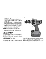
Your drill is equipped with a separate mode control collar (Fig. 1, C) to switch 

between drilling, screwdriving and hammerdrilling mode. 

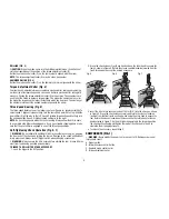
SCREWDRIVING (FIG. 2)

  1.   Select the desired speed/torque range using the three-speed gear shifter (E) on 

the top of tool to match the speed and torque to the planned application. To set 

the torque level to the proper setting on the clutch collar, initially set the clutch 

collar at a lower setting to ensure the fastener to be set to your specification. 

  NOTE: 

Use the lowest torque setting required to seat the fastener at the desired 

depth. The lower the number, the lower the torque output.

  2.  Rotate the mode control collar (C) so the screw symbol is aligned with the arrow. 
  3.  Set the torque adjustment collar (D) to the appropriate number setting for the 

torque desired.


NOTE: 

The torque adjustment collar may be set on any number and change 

between screwdriving and drilling modes using the mode control collar. 

FIG. 2

D

C

E

SCREWDRIVING

D

E

FIG. 4

HAMMERDRILLING

FIG. 3

DRILLING

C

Summary of Contents for DC901-XE

Page 1: ...DC901 XE HEAVY DUTY 36V 13 MM 1 2 CORDLESS HAMMERDRILL INSTRUCTION MANUAL ...

Page 2: ......

Page 3: ...rigerators There is an increased risk of electric shock if your body is earthed or grounded c Do not expose power tools to rain or wet conditions Water entering a power tool will increase the risk of electric shock d Do not abuse the cord Never use the cord for carrying pulling or unplugging the power tool Keep cord away from heat oil sharp edges or moving parts Damaged or entangled cords increase...

Page 4: ...poorly maintained power tools f Keep cutting tools sharp and clean Properly maintained cutting tools with sharp cutting edges are less likely to bind and are easier to control g Use the power tool accessories and tool bits etc in accordance with these instructions and in the manner intended for the particular type of power tool taking into account the working conditions and the work to be performe...

Page 5: ...vels generated by hammerdrilling Wear safety goggles or other eye protection Hammering and drilling operations cause chips to fly Flying particles can cause permanent eye damage Always use the side handle supplied with the tool Keep a firm grip on the tool at all times Do not attempt to operate this tool without holding it with both hands Hammer bits and tools get hot during operation Wear gloves ...

Page 6: ...ly may result in a risk of electric shock electrocution or fire Disconnect the charger from the outlet before attempting any cleaning This will reduce the risk of electric shock Removing the battery pack will not reduce this risk NEVER attempt to connect 2 chargers together WARNING ALWAYS wear proper personal hearing protection that conforms to ANSI S12 6 S3 19 during use Under some conditions and...

Page 7: ...ay cause respiratory irritation Provide fresh air If symptoms persists seek medical attention WARNING Burn hazard Battery liquid may be flammable if exposed to spark or flame Charge the battery packs only in DEWALT chargers DO NOT splash or immerse in water or other liquids Do not store or use the tool and battery pack in locations where the temperature may reach or exceed 40 C 105 F such as outsi...

Page 8: ...h together with two fast blinks followed by a pause This indicates that the power souce is out of limits BAD BATTERY The charger can detect a weak or damaged battery The three red lights will flash together with rapid blinking The battery will no longer charge and should be returned to a service center or a collection site for recycling BAD CHARGER The charger will detect if it is not functioning ...

Page 9: ...er CAUTION Never attempt to open the battery pack for any reason If the plastic housing of the battery pack breaks or cracks return to a service center for recycling SAVE THESE INSTRUCTIONS FOR FUTURE USE KEY FEATURES AND FUNCTIONS Variable Speed Switch Fig 1 To turn the tool on squeeze the trigger switch A To turn the tool off release the trigger switch Your tool is equipped with a brake The chuc...

Page 10: ...the clutch collar at a lower setting to ensure the fastener to be set to your specification NOTE Use the lowest torque setting required to seat the fastener at the desired depth The lower the number the lower the torque output 2 Rotate the mode control collar C so the screw symbol is aligned with the arrow 3 Set the torque adjustment collar D to the appropriate number setting for the torque desire...

Page 11: ...g gears If you have trouble changing gears make sure that the gear shifter is engaged in one of the three speed settings Self Tightening Chuck Operation Fig 5 7 WARNING Do not attempt to tighten drill bits or any other accessory by gripping the front part of the chuck and turning the tool on Damage to the chuck and personal injury may result Always lock off trigger switch when changing accessories...

Page 12: ...e tool handle Insert it into the charger Fig 9 as described in the charger section of this manual Side Handle WARNING To reduce the risk of personal injury ALWAYS operate the tool with the side handle properly installed Failure to do so may result in the side handle slipping during tool operation and subsequent loss of control Hold tool with both hands to maximize control Side handle clamps to the...

Page 13: ...protection when performing this WARNING Never use solvents or other harsh chemicals for cleaning the non metallic parts of the tool These chemicals may weaken the plastic materials used in these parts Use a cloth dampened only with water and mild soap Never let any liquid get inside the tool never immerse any part of the tool into a liquid CHARGER CLEANING INSTRUCTIONS WARNING Shock hazard Disconn...

Page 14: ...the warranty DEWALT tools are covered by our FREE ONE YEAR SERVICE CONTRACT DEWALT will also maintain the tool for free at any time during the first year of purchase This includes labour parts and lubrication required to restore the product to sound mechanical and or electrical condition Normal wear parts are not covered in this service Carbon brushes worn more then 50 will be replaced NOTE Three ...

Page 15: ......

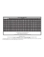
Page 16: ... X X X X 60 60 X X X X DC9096 18 2 4 X X X X 60 X 60 20 X 60 X 60 60 X X X 60 60 60 DC9180 18 2 0 X X X X X X X X X X X X X X X X 60 X 60 DW9096 18 2 4 X X X X 60 X 60 20 X 60 X 60 60 X X X 60 60 60 DE9095 XJ 18 2 0 X X X X 60 X 60 20 X 60 X 60 60 X X X 60 60 60 DC9091 14 4 2 4 60 60 60 60 60 15 60 15 60 60 60 60 60 X X X 60 60 60 DC9144 14 4 2 0 X X X X X X X X X X X X X X X X 60 X 60 DE9091 XJ 1...

Reviews: