8
English
ASSEmBLy (FIG. 3)
CAUTION:
Ensure the lock-off switch is in the locked
position to prevent the trigger switch from moving and the battery is
removed before attaching or removing the tube (E). The tube must be
attached to the housing (3A) before use.
•
tuBe aSSeMBLy:
To attach the
FIG. 3
E
3A
3B
3C
3D
tube to the blower, line up the pegs
(3B) on the bottom of the tube with
the notch (3C) on the bottom of the
housing opening as shown in
figure 3. Push the tube into the
blower housing until the lock
engages the tube.
• Pull on the tube to ensure it is
securely in place.
• To remove the tube, insert a screwdriver into the unlocking hole
(3D) on the side of the housing. Lift the tab inside and pull tube out.
OPERATIOn
WARNING:
Do not operate blower without tube
securely in place. Never reach down into housing through tube hole.
WARNING:
Always slide the lock-off switch to the
locked position and remove the battery when:
• You leave blower unattended.
• Checking, adjusting, cleaning, or working on blower.
Installing and Removing the Battery Pack
(Fig. 2, 4, 5)
WARNING:
Before removing or installing battery,
make certain the lock-off switch (C) is in the locked position to prevent
switch actuation.
7. Do not freeze or immerse the charger in water or any other liquid.
WARNING:
Shock hazard. Don’t allow any liquid to
get inside the charger. Electric shock may result.
WARNING:
Burn hazard. Do not submerge the battery
pack in any liquid or allow any liquid to enter the battery pack. Never
attempt to open the battery pack for any reason. If the plastic housing of
the battery pack breaks or cracks, return to a service center for recycling.
Storage Recommendations
1. The best storage place is one that is cool and dry, away from direct
sunlight and excess heat or cold.
2. For long storage, it is recommended to store a fully charged battery
pack in a cool dry place out of the charger for optimal results.
note:
Battery packs should not be stored completely depleted of
charge. The battery pack will need to be recharged before use.
SAVE THESE InSTRuCTIOnS
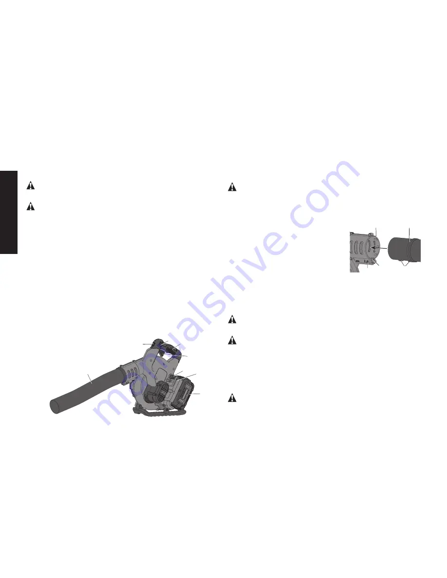
Components (Fig. 2)
A. Trigger switch
E. Tube
B. Speed lock lever
F. Battery housing
C. Lock-off switch
G. Battery pack
D. Handle
H. Battery release button
G
F
E
A
FIG. 2
D
B
C
H


