background image

English

9

Variable Speed Trigger Switch (Fig. A)

Depressing the variable speed trigger switch 

 4 

 turns the 

tool on, releasing the variable speed trigger switch turns 
the tool off. The variable speed trigger switch permits speed 
control—the farther the trigger is depressed, the higher the 
speed of the drill.

Forward/Reverse Button (Fig. A)

A forward/reverse button 

 3 

 determines the direction of the 

tool. It is located in front of the trigger switch.
To select forward rotation, release the trigger switch 

 4 

 and 

depress the forward/reverse button on the right side of the 
tool.
To select reverse, depress the forward/reverse button on 
the left side of the tool. When changing the position of the 
button, be sure the trigger is released.

nOTE:

 The first time the tool is run after changing the 

direction of rotation, you may hear a click on start up. This is 
normal and does not indicate a problem.

Keyed Chuck

Open the chuck jaws by turning collar by hand and insert 
the shank of the bit about 3/4" (19 mm) into chuck. Tighten 
the chuck collar by hand. Place chuck key (

 10 

, Fig. A) in 

each of the three holes, and tighten in clockwise direction. 
It’s important to tighten chuck with all three holes. To 
release the bit, turn the chuck counterclockwise in just one 
hole, then loosen the chuck by hand.

nOTE: 

When using hex shank or three-sided shank bits, be 

sure to align the flat sides of the bit with the chuck jaws to 
ensure the bit is properly engaged by the jaws.

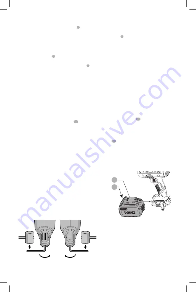
Removal of Keyed Chuck (Fig. G)

Remove the left-handed chuck screw using a T25 torx 
wrench, rotating clockwise to loosen.Tighten the chuck 
around the shorter end of a hex wrench (not supplied) 
of 3/8" (10 mm) size. With the tool braced securely, use 
a soft hammer and strike the hex wrench sharply in the 
counterclockwise direction when viewed from the front 
of the tool. This will loosen the chuck so that it can be 
removed by hand.

Keyed Chuck Installation (Fig. H)

Screw the chuck on by hand as far as it will go. Insert the 
shorter end of a hex wrench (not supplied) of 3/8" (10 mm) 
size and strike it in the clockwise direction with a soft 
hammer. Reinstall the left handed clutch screw.

FIG. H

FIG. G

Worklight (Fig. A)


CAUTION: Do not stare into worklight. 

Serious eye 

injury could result.

The worklight 

 9 

 is located on the foot of the tool. The 

worklight is activated when the trigger switch is depressed, 
and will automatically turn off 20 seconds after the trigger 
switch is released. If the trigger switch remains depressed, 
the worklight will remain on.

nOTE:

 The worklight is for lighting the immediate work 

surface and is not intended to be used as a flashlight.

OPERATION


WARNING: To reduce the risk of serious personal 
injury, turn unit off and remove the battery pack 
before making any adjustments or removing/
installing attachments or accessories.

 An 

accidental start-up can cause injury.

Installing and Removing the Battery Pack 

(Fig. I)

nOTE:

 For best results, make sure your battery pack is 

fully charged.
To install the battery pack 

 12 

 into the tool handle, align the 

battery pack with the rails inside the tool’s handle and slide 
it into the handle until the battery pack is firmly seated in 
the tool and ensure that it does not disengage.
To remove the battery pack from the tool, press the release 
button 

 13 

 and firmly pull the battery pack out of the tool 

handle. Insert it into the charger as described in the charger 
section of this manual.
Squeeze the tool trigger for three seconds to dissipate 
the slight electric charge that may still be in the tool. The 
worklight may come on for a brief moment.

Fig. I

13

12

Proper Hand Position (Fig. J)


WARNING:

 To reduce the risk of serious personal injury, 

ALWAYS

 use proper hand position as shown. 


WARNING:

 To reduce the risk of serious personal injury, 

ALWAYS

 hold securely in anticipation of a sudden 

reaction.

Always


hold tool firmly with both hands in the proper 

position for operation as shown.

Summary of Contents for DCD460T2

Page 1: ...minor or moderate injury NOTICE Indicates a practice not related to personal injury which if not avoided may result in property damage WARNING Read all safety warnings and all instructions Failure to follow the warnings and instructions may result in electric shock fire and or serious injury WARNING To reduce the risk of injury read the instruction manual If you have any questions or comments abou...

Page 2: ...ropriate conditions will reduce personal injuries c Prevent unintentional starting Ensure the switch is in the off position before connecting to power source and or battery pack picking up or carrying the tool Carrying power tools with your finger on the switch or energizing power tools that have the switch on invites accidents d Remove any adjusting key or wrench before turning the power tool on ...

Page 3: ...ction activities contains chemicals known to the State of California to cause cancer birth defects or other reproductive harm Some examples of these chemicals are lead from lead based paints crystalline silica from bricks and cement and other masonry products and arsenic and chromium from chemically treated lumber Your risk from these exposures varies depending on how often you do this type of wor...

Page 4: ...crews keys etc Transporting batteries can possibly cause fires if the battery terminals inadvertently come in contact with conductive materials such as keys coins hand tools and the like The US Department of Transportation Hazardous Material Regulations HMR actually prohibit transporting batteries in commerce or on airplanes in carry on baggage UNLESS they are properly protected from short circuit...

Page 5: ... other than charging DeWALT rechargeable batteries Any other uses may result in risk of fire electric shock or electrocution Do not expose the charger to rain or snow Pull by the plug rather than the cord when disconnecting the charger This will reduce the risk of damage to the electric plug and cord Make sure that the cord is located so that it will not be stepped on tripped over or otherwise sub...

Page 6: ...the battery pack fully before first use Fig C 12 13 Charger Operation Refer to the indicators below for the charge status of the battery pack DCB101 Charging Fully Charged Hot Cold Pack Delay Problem Pack or Charger DCB107 DCB112 DCB113 DCB115 DCB118 Charging Fully Charged Hot Cold Pack Delay DCB107 DCB112 DCB113 DCB115 DCB118 The red light will continue to blink but a yellow indicator light will ...

Page 7: ...u may also charge a partially used pack whenever you desire with no adverse effect on the battery pack 5 Foreign materials of a conductive nature such as but not limited to grinding dust metal chips steel wool aluminum foil or any buildup of metallic particles should be kept away from charger cavities Always unplug the charger from the power supply when there is no battery pack in the cavity Unplu...

Page 8: ...ion normally when the trigger is depressed again and the indicator light will go out Bail Handle Fig E A bail handle 1 is provided for carrying the tool and for use as an additional handle Assemble the bail handle in one of the positions shown in Figure E When changing the location of the bail handle from one position to the other completely remove the two bail handle bolts 5 securing it Flip the ...

Page 9: ...en the chuck so that it can be removed by hand Keyed Chuck Installation Fig H Screw the chuck on by hand as far as it will go Insert the shorter end of a hex wrench not supplied of 3 8 10 mm size and strike it in the clockwise direction with a soft hammer Reinstall the left handed clutch screw FIG H FIG G Worklight Fig A CAUTION Do not stare into worklight Serious eye injury could result The workl...

Page 10: ...pressure on the tool Holes in wood can be made with the same twist drills used for metal These bits may overheat unless pulled out frequently to clear chips from the flutes Work that is apt to splinter should be backed up with a block of wood MAINTENANCE WARNING To reduce the risk of serious personal injury turn unit off and remove the battery pack before making any adjustments or removing install...

Page 11: ...further detail of warranty coverage and warranty repair information visit www dewalt com or call 1 800 4 DeWALT 1 800 433 9258 This warranty does not apply to accessories or damage caused where repairs have been made or attempted by others This warranty gives you specific legal rights and you may have other rights which vary in certain states or provinces In addition to the warranty DeWALT tools a...

Page 12: ...que une pratique ne posant aucun risque de dommages corporels mais qui par contre si rien n est fait pour l éviter pourrait poser des risques de dommages matériels AVERTISSEMENT lire tous les avertissements de sécurité et toutes les directives Le non respect des avertissements et des directives pourrait se solder par un choc électrique un incendie et ou une blessure grave AVERTISSEMENT afin de réd...

Reviews: