background image

9

NOTE: 

Continuous use in variable speed range is not recommended. It may damage 

the switch and should be avoided.

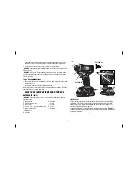
Forward/Reverse Control Button (Fig. 2) 

A forward/reverse control button (B) determines the direction of the tool and also 

serves as a lock-off button. 

To select forward rotation

, release the trigger switch 

and depress the forward/reverse control button on the right side of the tool. 

To select 

reverse

, release the trigger switch and depress the forward/reverse control button on 

the left side of the tool. The center position of the control button locks the tool in the 

off position. When changing the position of the control button, be sure the trigger is 

released.

NOTE:

 The first time the tool is run after changing the direction of rotation, you may 

hear a click on start up. This is normal and does not indicate a problem. 

Worklights (Fig. 2)

There are three worklights (G) located around the chuck collar (C). The worklights 

are activated when the trigger switch is depressed, and will automatically turn 

off 20 seconds after the trigger switch is released. If the trigger switch remains 

depressed, the worklights will remain on.

NOTE: 

The worklights are for lighting the immediate work surface and are not 

intended to be used as a flashlight. 

FIG. 4

C

D

FIG. 5

C

D

Quick-Release Chuck (Fig. 2, 4, 5)

NOTE:

 The chuck accepts 6.35 mm (1/4") hex accessories and 25.4 mm (1") bit tips 

only.

Place the forward/reverse button (B) in the lock-off (center) position or remove battery 

pack before changing accessories.

To install an accessory

, fully insert the accessory. The accessory is locked into place 

(Fig. 4).

To remove an accessory

, pull the chuck collar (C) away from the front of the tool. 

Remove the accessory (Fig. 5).

Anvil With Detent Pin (Fig. 2)

DCF880-XE 

Place the switch in the locked off (center) position or remove battery pack before 

changing accessories.

To install a socket on the anvil,

 align the hole in the side of the socket with the detent 

pin (L) on the anvil (K). Press the socket on until the detent pin engages in the hole. 

Depression of detent pin may be necessary to aid installation of socket.

WARNING:

 Use only impact sockets. Non-impact sockets may break and cause a 

hazardous condition. Inspect sock et prior to use to ensure that it con tains no cracks.

To remove a socket,

 depress the detent pin through the hole and pull the socket off.

Usage

Your impact tool can generate the following output torque: 

 Cat 

Ft.-Lbs. 

In.-Lbs. 

Nm

 DCF880-XE 

150 

1800 

203

 DCF885-XE 

117 

1400 

155

CAUTION: 

Ensure fastener and/or system will withstand the level of torque 

generated by the tool. Excessive torque may cause breakage and possible personal 

injury.
  1. Place the socket on the fastener head. Keep the tool pointed straight at the 

fastener. 

  2. Press switch to start operation. Release switch to stop operation. Always check 

torque with a torque wrench, as the fastening torque is affected by many factors 

including the following:

    • Low voltage, due to a nearly discharged battery, will reduce fastening torque.
    • Failure to use the correct socket size will cause a reduction in fastening torque.

Summary of Contents for DCF835-XE

Page 1: ...DCF880 XE 18 V CORDLESS 13 mm 1 2 IMPACT WRENCH DCF885 XE 18 V CORDLESS 6 35 mm 1 4 IMPACT DRIVER INSTRUCTION MANUAL ...

Page 2: ......

Page 3: ... clean and well lit Cluttered or dark areas invite accidents b Do not operate power tools in explosive atmospheres such as in the presence of flammable liquids gases or dust Power tools create sparks which may ignite the dust or fumes c Keep children and bystanders away while operating a power tool Distractions can cause you to lose control 2 ELECTRICAL SAFETY a Power tool plugs must match the out...

Page 4: ...ers e Maintain power tools Check for misalignment or binding of moving parts breakage of parts and any other condition that may affect the power tool s operation If damaged have the power tool repaired before use Many accidents are caused by poorly maintained power tools f Keep cutting tools sharp and clean Properly maintained cutting tools with sharp cutting edges are less likely to bind and are ...

Page 5: ...ul to your hands and arms Use gloves to provide extra cushion and limit exposure by taking frequent rest periods WARNING We recommend the use of a residual current device with a residual current rating of 30mA or less WARNING ALWAYS wear approved protective safety equipment complying with the following standards Eye protection AS NZS1337 Eye Protectors for Industrial Applications Hearing protectio...

Page 6: ...id gets into the eye rinse water over the open eye for 15 minutes or until irritation ceases If medical attention is needed the battery electrolyte is composed of a mixture of liquid organic carbonates and lithium salts Contents of opened battery cells may cause respiratory irritation Provide fresh air If symptoms persist seek medical attention WARNING Burn hazard Battery liquid may be flammable i...

Page 7: ...ult in risk of fire electric shock or electrocution When operating a charger outdoors always provide a dry location and use an extension cord suitable for outdoor use Use of a cord suitable for outdoor use reduces the risk of electric shock Do not place any object on top of the charger or place the charger on a soft surface that might block the ventilation slots and result in excessive internal he...

Page 8: ...t DC to AC the charger may temporarily suspend operation flashing the red light with two fast blinks followed by a pause This indicates the power source is out of limits Important Charging Notes 1 Longest life and best performance can be obtained if the battery pack is charged when the air temperature is between 18 24 C 65 F and 75 F DO NOT charge the battery pack in an air temperature below 4 C 4...

Page 9: ...f the charger for optimal results NOTE Battery packs should not be stored completely depleted of charge The battery pack will need to be recharged before use SAVE THESE INSTRUCTIONS FOR FUTURE USE COMPONENTS FIG 2 WARNING Never modify the power tool or any part of it Damage or personal injury could result A Trigger switch H Belt hook B Forward reverse button I Screw C Chuck collar J Bit clip D 6 3...

Page 10: ... switch Your tool is equipped with a brake The chuck will stop when the trigger switch is fully released The variable speed switch enables you to select the best speed for a particular application The more you squeeze the trigger the faster the tool will operate For maximum tool life use variable speed only for starting holes or fasteners Belt Hook and Bit Clip Fig 2 WARNING To reduce the risk of ...

Page 11: ...ff center position or remove battery pack before changing accessories To install an accessory fully insert the accessory The accessory is locked into place Fig 4 To remove an accessory pull the chuck collar C away from the front of the tool Remove the accessory Fig 5 Anvil With Detent Pin Fig 2 DCF880 XE Place the switch in the locked off center position or remove battery pack before changing acce...

Page 12: ... tool never immerse any part of the tool into a liquid CHARGER CLEANING INSTRUCTIONS WARNING Shock hazard Disconnect the charger from the AC outlet before cleaning Dirt and grease may be removed from the exterior of the charger using a cloth or soft non metallic brush Do not use water or any cleaning solutions Repairs The charger and battery pack are not serviceable There are no serviceable parts ...

Page 13: ......

Page 14: ......

Page 15: ......

Page 16: ...X X X X X X X 30 30 40 X X DCB182 18 4 0 X X X X X X X X X X X X X X X X X X 90 90 117 X X DW9096 18 2 4 X X X X 60 X 60 20 X 60 X 60 60 X X X 60 X 60 X X 60 60 DE9095 XJ 18 2 0 X X X X 60 X 60 20 X 60 X 60 60 X X X 60 X 60 X X 60 60 DC9091 14 4 2 4 60 60 60 60 60 15 60 15 60 60 60 60 60 X X X 60 X 60 X X 60 60 DC9144 14 4 2 0 X X X X X X X X X X X X X X X X 60 X 60 X X X 60 DE9094 14 4 1 3 45 45 ...

Reviews: