P1000
Model
P1000
Cat. No.
ddF211000P
4
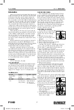
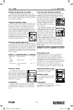
eDge DiSTance
do not fasten closer than 3” from the
edge of concrete. if the concrete cracks,
the fastener may not hold. closer edge
distances for applications such as sill
plates may be permitted if
specific fastener testing has been con-
ducted.
Spacing
setting fasteners too close together in concrete or
masonry can cause cracking. the recommended minimum
distance between fasteners is 3” center to center.
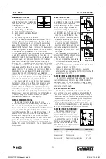
FaSTeneR lengTh SelecTion in concReTe
for permanent applications using
pins in concrete, first determine the
thickness of the fixture to be fastened.
to this, add the required embedment
or penetration into the base material.
this will be the fastener shank length
required. for applications in the
face shell of masonry block, select a
fastener length which will not exceed
the thickness of the face shell.
for removable applications with
threaded studs, the shank length
required is equal to the embedment
depth required. to determine the
minimum threaded length, add the thickness of the fixture
and the nut / washer thickness. the nut and washer
thickness is equal to the nominal thread diameter. do not
over tighten threaded parts. maximum tightening torque
values are listed in the table below. use of a nut setter is
recommended to reduce the possibility of over tightening the
fasteners. for critical applications, perform a job site test.
MaxiMuM ToRque FoR
1/4” STuD (FT.-lBS.)
MaxiMuM ToRque FoR
3/8” STuD (FT.-lBS.)
2
4
inSTallaTion in STeel
the following guidelines are based on the installation of
a fastener in astm a 36 structural steel with the point fully
penetrating the steel member. recommended steel material
thickness ranges from a minimum of 1/8” to a maximum of
3/8”. for use in higher strength structural steel, applications
where the point does not penetrate the steel member, or a
thickness of steel greater than 3/8”, job site performance
tests are recommended.
BaSe MaTeRial ThickneSS
steel base materials should be a
minimum of 1/8” in thickness.
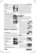
eDge DiSTance
for installations in a 36 steel, 1/2”
is the recommended minimum edge
distance.
Spacing
the recommended minimum distance
between fastenings is 1-1/2” center to center for installations
in astm a 36 steel.
FaSTeneR lengTh SelecTion in STeel
for permanent applications when using pins in steel, first
determine the thickness of the fixture to be fastened. to this,
add the thickness of the steel base material plus a minimum
of 1/4” to allow for proper point penetration. this will be the
minimum fastener shank length required. do not select a
fastener length longer than that required for the application.
an excessively long shank can burnish or polish the hole
created in the steel resulting in a reduction in load capacity.
for removable applications with threaded studs, the
shank length required is equal to the thickness of the steel
base material plus a minimum of 1/4” to allow for proper
point penetration. this will be the minimum fastener shank
length required. do not select a shank length longer than
that required for the application.
Tool operaTion
be sure to read and understand all of
the safety precautions and training in this manual before
attempting to operate the tool. (check to be sure the tool is
not loaded, the piston moves freely within the barrel, and no
foreign objects or fasteners are in the barrel.) Perform
the daily function test before using the tool.
opeRaTion
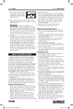
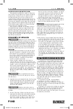
1. always point the tool in a safe
direction away from bystanders
and the operator. slide the barrel
forward. this can be done by
snapping your wrist. the barrel
should be pulled fully forward to reset the piston for
the next fastening. loss of power may result from an
im properly positioned piston.
2. always load the fastener before
inserting powder load to prevent
injury to the operator or bystanders
in the event of an accidental
discharge. Place the fastener, point
out, into the end of the nose piece until the fluted tip
fits inside. do not use excessive
force when inserting the fastener.
if excessive force is required, stop
and determine why the fastener can
not be inserted. correct the problem
before proceeding.
do not use fasteners longer than 3” as listed
in the fastener selection section of this manual.
3. make sure the breech is clear.
insert the powder load starting with
the lowest power level. if this load
does not fully set the fastener, try
the next higher power level until the
proper level is found.
over driving or over powering a fastener can
cause a safety hazard.
4. Pull the barrel all the way back to
close the tool. do not attempt to
close the tool by exerting force on
the front of the nose piece. never
place your fingers or hands over
muzzle bushing. the safe position for hands and fingers
are as shown in the diagram. hands must never be
R
22
00
R
22
00
3"
3"
Fixture
Embedment
Thread Length
Embedment
1/8"
1/2"
1-1/2"
POW2271_P1000_booklet.indd 4
3/10/14 12:43 PM
Summary of Contents for DDF211000P
Page 30: ...P1000 Model P1000 Modelo P1000 ModÈlE P1000 30 POW2271_P1000_booklet indd 30 3 10 14 12 43 PM ...
Page 31: ...P1000 Model P1000 Modelo P1000 ModÈlE P1000 31 POW2271_P1000_booklet indd 31 3 10 14 12 43 PM ...
Page 32: ...P1000 Model P1000 Modelo P1000 ModÈlE P1000 32 POW2271_P1000_booklet indd 32 3 10 14 12 43 PM ...


