40
EnGLIsh
WARNING:
The conditions of the area are indicative of the results presented.
If the practice differs from these conditions, the measurements have to be
adjusted accordingly.
Checking Accuracy – Horizontal Beam, Scan Direction (Fig. F)
Checking the horizontal scan calibration of the laser requires two walls at least 30' (9 m)
apart. It is important to conduct a calibration check using a distance no shorter than the
distance of the applications for which the tool will be used.
1. Attach the laser to a wall using its pivot bracket. Make sure the laser is facing
straight ahead.
2. Turn on the laser's horizontal beam and pivot the laser approximately 45˚ so that the
right-most end of the laser line is striking the opposing wall at a distance of at least 30'
(9 m). Mark the center of the beam (a).
3. Pivot the laser approximately 90˚ to bring the left-most end of the laser line around to
the mark made in Step 2. Mark the center of the beam (b).
4. Measure the vertical distance between the marks.
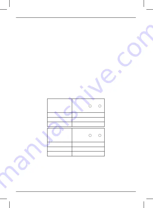
• If the measurement is greater than the values shown below, the laser must be serviced
at an authorized service center.
Distance
Between
Walls
allowable Distance
Between
a
and
b
30'
1/8"
40'
5/32"
50'
7/32"
Distance
Between
Walls
allowable Distance
Between
a
and
b
9.0 m
3.1 mm
12.0 m
4.2 mm
15.0 m
5.2 mm
Checking Accuracy – Horizontal Beam, Pitch Direction (Fig. G)
Checking the horizontal pitch calibration of the laser requires a single wall at least 30' (9
m) long. It is important to conduct a calibration check using a distance no shorter than the
distance of the applications for which the tool will be used.
1. Attach the laser to one end of a wall using its pivot bracket.
2. Turn on the laser's horizontal beam and pivot the laser toward the opposite end of the
wall and approximately parallel to the adjacent wall.
Summary of Contents for DW088KD
Page 1: ...DW088 DW088CG www 2helpU com Final page size A6 105 mm x 148 mm ...
Page 3: ...1 Fig A 11 8 9 7 10 1 2 3 11 6 5 4 12 12 ...
Page 4: ...2 Fig B Fig C1 13 10 14 8 15 ...
Page 5: ...3 Fig C2 Fig C3 8 9 15 15 16 ...
Page 6: ...4 Fig C4 Fig D 17 ...
Page 7: ...5 Fig E Fig F STEP 1 a b STEP 2 45 90 STEP 3 STEP 4 STEP 2 STEP 3 ...


