E N G L I S H
16
en - 4
Assembly and adjustment
Prior to assembly and adjustment always
unplug the tool.
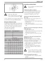
Adjusting the depth of cut (fig. B)
• Turn the planing depth adjustment knob (4).
One revolution of the adjustment knob equals
a 4.0 mm change in depth. One graduation
corresponds to a depth of cut of 0.1 mm.
Attaching and removing the parallel fence
(fig. A & C)
The parallel fence (13) is used for optimum tool
control on narrow workpieces.
• Fit the parallel fence (13) to the threaded hole (6)
from either side.
• Tighten the wing bolt (14).
• To remove the parallel fence, proceed in reverse
order.
Attaching, removing and adjusting the rabbeting
depth stop (fig. A)
• Install the depth stop (8).
• Tighten the wing bolt at the desired height in the
threaded hole using the scale.
• To remove the depth stop, proceed in reverse
order.
Attaching and removing the stationary stand
(DE6661) (fig. D & E)
The stationary stand in figure D is the DE6661.
This stand is available as an option as well as the
thicknessing and surfacing stand DE80.
• Open the guard (17) on the stationary stand.
• Place the planer on the stationary stand (15).
• Tighten the star knob (16).
• Attach the parallel fence (13) as described.
• To remove the stationary stand, proceed in
reverse order.
The part of the cutter that is not being
used must always be covered by the
guard (17) or by the parallel fence (13).
Removing reversible cutters (fig. F)
• Loosen the three bolts (21) using the spanner
supplied.
• Flap the side guard (9) up.
• Never use a light socket.
• Never connect the live (L) or neutral (N)
wires to the earth pin marked E or
.
For 115 V units with a power rating exceeding 1500 W,
we recommend to fit a plug to BS4343 standard.
Using an extension cable
If an extension cable is required, use an approved
extension cable suitable for the power input of this
tool (see technical data). The minimum conductor
size is 1.5 mm
2
. When using a cable reel, always
unwind the cable completely.
Also refer to the table below.
Conductor size (mm
2
)
Cable rating (Amperes)
0.75
6
1.00
10
1.50
15
2.50
20
4.00
25
Cable length (m)
7.5
15
25
30
45
60
Voltage
Amperes
Cable rating (Amperes)
115
0 - 2.0
6
6
6
6
6
10
2.1 - 3.4
6
6
6
6
15
15
3.5 - 5.0
6
6
10
15
20
20
5.1 - 7.0
10
10
15
20
20
25
7.1 - 12.0
15
15
20
25
25
-
12.1 - 20.0
20
20
25
-
-
-
230
0 - 2.0
6
6
6
6
6
6
2.1 - 3.4
6
6
6
6
6
6
3.5 - 5.0
6
6
6
6
10
15
5.1 - 7.0
10
10
10
10
15
15
7.1 - 12.0
15
15
15
15
20
20
12.1 - 20.0
20
20
20
20
25
-
Summary of Contents for DW678
Page 1: ... DW678 ...
Page 3: ...A2 3 7 8 10 9 12 2 1 4 5 6 7 11 A1 ...
Page 4: ...B D C 14 13 4 16 13 20 17 18 19 15 ...
Page 5: ...E G F 21 22 9 1 MM 13 24 3 23 25 ...
Page 85: ......
Page 86: ......
Page 87: ......


