17
E N G L I S H
en - 4
Electrical safety
The electric motor has been designed for one
voltage only. Always check that the power supply
corresponds to the voltage on the rating plate.
Your D
E
WALT tool is double insulated in
accordance with EN 50144; therefore no
earth wire is required.
Mains plug replacement
(U.K. & Ireland only)
• Should your mains plug need replacing and you
are competent to do this, proceed as instructed
below. If you are in doubt, contact an authorized
D
E
WALT repair agent or a qualified electrician.
• Disconnect the plug from the supply.
• Cut off the plug and dispose of it safely; a plug
with bared copper conductors is dangerous if
engaged in a live socket outlet.
• Only fit 13 Amperes BS1363A approved plugs
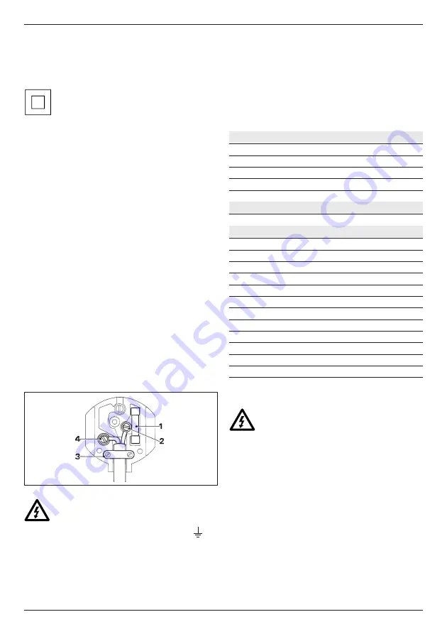
fitted with the correctly rated fuse (1).
• The cable wire colours, or a letter, will be marked
at the connection points of most good quality
plugs. Attach the wires to their respective points
in the plug (see below). Brown is for Live (L) (2)
and Blue is for Neutral (N) (4).
• Before replacing the top cover of the mains plug
ensure that the cable restraint (3) is holding the
outer sheath of the cable firmly and that the two
leads are correctly fixed at the terminal screws.
Never use a light socket.
Never connect the live (L) or neutral (N)
wires to the earth pin marked E or
.
For 115 V units with a power rating exceeding
1500 W, we recommend to fit a plug to BS4343
standard.
Using an extension cable
If an extension cable is required, use an approved
extension cable suitable for the power input of this
tool (see technical data). The minimum conductor
size is 1.5 mm
2
. When using a cable reel, always
unwind the cable completely.
Also refer to the table below.
Conductor size (mm
2
)
Cable rating (Amperes)
0.75
6
1.00
10
1.50
15
2.50
20
4.00
25
Cable length (m)
7.5
15
25
30
45
60
Voltage
Amperes
Cable rating (Amperes)
115
0 - 2.0
6
6
6
6
6
10
2.1 - 3.4
6
6
6
6
15
15
3.5 - 5.0
6
6
10
15
20
20
5.1 - 7.0
10
10
15
20
20
25
7.1 - 12.0
15
15
20
25
25
-
12.1 - 20.0
20
20
25
-
-
-
230
0 - 2.0
6
6
6
6
6
6
2.1 - 3.4
6
6
6
6
6
6
3.5 - 5.0
6
6
6
6
10
15
5.1 - 7.0
10
10
10
10
15
15
7.1 - 12.0
15
15
15
15
20
20
12.1 - 20.0
20
20
20
20
25
-
Assembly and adjustment
Prior to assembly and adjustment always
unplug the tool.
Replacing the blade (fig. A)
• Remove the knurled nuts (4) and the cover
plate (3).
• Hold the spindle using the sickle spanner and
remove the front flange by turning it clockwise.
• Change the blade.
• Tighten the flange securely by turning it
counterclockwise while holding the spindle with
the sickle spanner.
• Mount the cover plate and tighten the knurled
nuts.
Summary of Contents for DW685K
Page 1: ...77 DW685K ...
Page 2: ...78 17 18 19 H K J 1 2 ...
Page 3: ...81 1 3 11 12 8 12 11 9 10 A1 ...
Page 4: ...82 1 3 8 4 2 7 4 6 5 2 B A2 C 13 14 5 ...
Page 5: ...83 11 D F G E 15 16 15 6 ...

