background image

6

CAUTION:

 Read and follow all manufacturers' safety warnings for any accessories 

used with this tool.

CAUTION:

 To avoid injury, ensure adaptor and accessory are securely tightened.

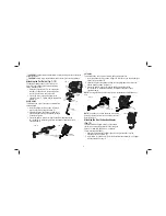
Attaching the Cut Guide (Fig. 7–12)

The depth/cut guide allows you to precisely cut  

material at a specified depth and more accurately 

track a marked cut line.
  1. Attach the cut guide block (F) by inserting the 

tabs (M) on the guide into the accessory side 

mount (E) on the main body of the tool.

  2. Secure the block to the main body with the 

supplied screw (O). Tighten with the supplied hex 

wrench (P).

DEPTH GUIDE

This feature allows you to precisely cut material at a 

specified depth.
  1. Insert the guide arm (G) as shown in Figure 8 

into the front slot on the guide block (F).

  2. Adjust the length of the guide by pulling out or 

pushing inward to achieve the desired cut depth 

as shown in Figure 9.

  3. Secure the guide in place by turning the depth/cut adjustment knob 

(N) clockwise. To release the guide turn the depth/cut adjustment knob 

counterclockwise.

N

FIG. 8

FIG. 9

F

G

E

M

O

P

F

FIG. 7

CUT GUIDE

This feature allows you to more accurately track a marked cut line.
  1. Insert the guide arm (G) as shown in figure 10 into the slots on the left and right 

sides of the guide block (F).

  2. Adjust the length of the guide by pulling out or pushing inward to achieve the 

desired length as shown in Figure 11.

  3. Secure the guide in place by turning the depth/cut adjustment knob 

(N) clockwise. To release the guide turn the depth/cut adjustment knob 

counterclockwise.

NOTE:

 The cut guide block and the cut guide arm are available on selected model 

only.

N

FIG. 10

FIG. 11

F
G

NOTE: 

The guide arm can also be placed in the guard 

assembly vertically in order to set the height off a cut. 
Refer to Figure 12. 

Attaching the Dust Extraction Adaptor 

(Fig. 13)

The Dust Extraction Adaptor allows you to connect 

the tool to an external dust extractor, either using the 

AirLock™ system (DWV9000-XJ) or a standard 

35 mm dust extractor fitment.
  1. Attach the dust extraction adaptor (Q) by inserting the tabs (M) in to the 

accessory side mount slots (E).

  2. Insert screw (O) and washer (R) into the dust extraction adaptor (Q) and tighten 

with the supplied hex key (P).

FIG. 12

Summary of Contents for DWE315-XE

Page 1: ...DWE315 XE OSCILLATING MULTI TOOL INSTRUCTION MANUAL ...

Page 2: ......

Page 3: ...in EN 60745 and may be used to compare one tool with another It may be used for a preliminary assessment of exposure WARNING The declared vibration emission level represents the main applications of the tool However if the tool is used for different applications with different accessories or poorly maintained the vibration emission may differ This may significantly increase the exposure level over...

Page 4: ...wer tool while you are tired or under the influence of drugs alcohol or medication A moment of inattention while operating power tools may result in serious personal injury b Use personal protective equipment Always wear eye protection Protective equipment such as dust mask non skid safety shoes hard hat or hearing protection used for appropriate conditions will reduce personal injuries c Prevent ...

Page 5: ...person responsible for their safety Children should be supervised to ensure that they do not play with the appliance Replacement of the supply cord If the supply cord or plug is damaged it must be replaced by the manufacturer or an authorised DEWALT Service Centre in order to avoid a hazard Extension Cords CAUTION Use only extension cords that are approved by the country s Electrical Authority Bef...

Page 6: ... into your mouth eyes or lay on the skin may promote absorption of harmful chemicals WARNING Use of this tool can generate and or disburse dust which may cause serious and permanent respiratory or other injury Always use AS NZS1716 approved respiratory protection appropriate for the dust exposure Direct particles away from face and body WARNING Always wear proper personal hearing protection that c...

Page 7: ...lamp lever NOTE Some accessories such as scrapers and blades can be mounted at an angle if required as shown in Figure 4 FIG 3 FIG 4 INSTALLING REMOVING SANDING SHEETS FIG 5 A diamond shaped platen uses a hook and loop adhesion system to attach the sanding sheets The platen allows you to use it on large flat surfaces and tight spots or corners 1 Attach the sanding platen I as described under Insta...

Page 8: ...t knob counterclockwise N FIG 8 FIG 9 F G E M O P F FIG 7 CUT GUIDE This feature allows you to more accurately track a marked cut line 1 Insert the guide arm G as shown in figure 10 into the slots on the left and right sides of the guide block F 2 Adjust the length of the guide by pulling out or pushing inward to achieve the desired length as shown in Figure 11 3 Secure the guide in place by turni...

Page 9: ...nding Sheets Q I FIG 14 Using the Dust Extraction Adaptor with Plunge Cutting Accessory Fig 15 1 Attach the dust extraction adaptor Refer to Attaching the Dust Extraction Adaptor 2 Push dust extraction arm R into the lower aperture of the dust extraction adaptor Q 3 Attach plunge cutting bit as described under Installing Removing Accessories 4 Adjust the dust extraction arm R for best results Vari...

Page 10: ...uct use of such accessories with this tool could be hazardous To reduce the risk of injury only DEWALT recommended accessories should be used with this product Recommended accessories for use with your tool are available at extra cost from your local service center If you need any assistance in locating any accessory please contact Stanley Black Decker 82 Taryn Drive Epping VIC 3076 Australia or c...

Page 11: ...tedly causes the circuit fuse to blow discontinue use immediately and have it serviced at an authorized service center Circuit breaker is tripped Reset circuit breaker If the product repeatedly causes thecircuit breaker to trip discontinue use immediately and have it serviced at an authorized service center Cord or switch is damaged Have cord or switch replaced at an authorized service center ...

Page 12: ...dewalt co nz JUN13 Part No N289479 DWE315 XE Copyright 2013 DEWALT The following are trademarks for one or more DEWALT power tools the yellow and black color scheme the D shaped air intake grill the array of pyramids on the handgrip the kit box configuration and the array of lozenge shaped humps on the surface of the tool ...

Reviews: