background image

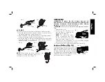
INSTALLING/REMOVING SANDING
SHEETS (FIG. 5)

A diamond shaped platen uses a hook 

and loop adhesion system to attach the 
sanding sheets. The platen allows you 
to use it on large flat surfaces and tight 
spots or corners.

 1. Attach the sanding platen (I) as 

described under 

Installing/

Removing Accessories

.

 2. Align the edges on the sanding 

sheet, with the edge of the sanding 
platen and press the sanding sheet 
(J) onto the platen.

  3. Firmly press the base with the sanding sheet attached against a 

flat surface and briefly switch the tool on. This provides for good 
adhesion between the platen and the sanding sheet and also 
helps to prevent premature wear.

  4. When the tip of the sanding sheet becomes worn, detach the 

sheet from the platen, rotate and reapply.

ATTACHING ACCESSORIES USING THE UNIVERSAL


ADAPTER (FIG. 6)

Non-D

E

WALT accessories can be 

attached using the universal adaptor.

  1. Place the washer (K) on the tool.
  2. Place accessory on to washer.
  3. Tighten and secure adaptor nut (L) 

using a hex wrench.

FIG. 5

J

I

FIG. 6

K

L

CAUTION:

 To avoid injury, do not use any accessory for an 

application where the adaptor may fail to hold the accessory.

CAUTION:

 Read and follow all manufacturers' safety warnings for 

any accessories used with this tool.

CAUTION:

 To avoid injury, ensure adaptor and accessory are 

securely tightened.

Attaching the Cut Guide (Fig. 7–11)

The depth/cut guide allows you to precisely 

cut material at a specified depth and more 
accurately track a marked cut line.

 1. Attach the cut guide block (F) by 

inserting the tabs (M) on the guide into 
the accessory side mount (E) on the 
main body of the tool.

  2. Secure the block to the main body with 

the supplied screw (O) and tighten with 
the supplied hex wrench (P).

DEPTH GUIDE

This feature allows you to precisely cut 

material at a specified depth.

  1. Insert the guide arm (G) as shown in 

Figure 8 into the front slot on the guide 
block (F).

  2. Adjust the length of the guide by pulling out or pushing inward to 

achieve the desired cut depth as shown in Figure 9.

  3. Secure the guide in place by turning the depth/cut adjustment 

knob clockwise. To release the guide, turn the depth/cut 
adjustment knob counterclockwise.

E

M

O

P

F

FIG. 7

English

6

Summary of Contents for DWE315K

Page 1: ...it Cluttered or dark areas invite accidents b Do not operate power tools in explosive atmospheres such as in the presence of flammable liquids gases or dust Power tools create sparks which may ignite the dust or fumes c Keep children and bystanders away while operating a power tool Distractions can cause you to lose control 2 ELECTRICAL SAFETY a Power tool plugs must match the outlet Never modify ...

Page 2: ...d and properly used Use of dust collection can reduce dust related hazards 4 POWER TOOL USE AND CARE a Do not force the power tool Use the correct power tool for your application The correct power tool will do the job better and safer at the rate for which it was designed b Do not use the power tool if the switch does not turn it on and off Any power tool that cannot be controlled with the switch ...

Page 3: ...ing more than one extension to make up the total length be sure each individual extension contains at least the minimum wire size The following table shows the correct size to use depending on cord length and nameplate ampere rating If in doubt use the next heavier gauge The smaller the gauge number the heavier the cord Minimum Gauge for Cord Sets Ampere Rating Volts Total Length of Cord in Feet m...

Page 4: ...ce and body WARNING Always wear proper personal hearing protection that conforms to ANSI S12 6 S3 19 during use Under some conditions and duration of use noise from this product may contribute to hearing loss The label on your tool may include the following symbols The symbols and their definitions are as follows V volts A amperes Hz hertz W watts min minutes or AC alternating or DC direct current...

Page 5: ...r when making repairs An accidental start up can cause injury WARNING Risk of lacerations or burns Do not touch the sharp edges of accessories at any time Do not touch workpiece or blade immediately after operating the tool They can become very hot Handle carefully Always allow accessories and workpiece to cool before handling Installing Removing Accessories Fig 2 4 TOOL FREE ACCESSORY CLAMP The D...

Page 6: ... wrench FIG 5 J I FIG 6 K L CAUTION To avoid injury do not use any accessory for an application where the adaptor may fail to hold the accessory CAUTION Read and follow all manufacturers safety warnings for any accessories used with this tool CAUTION To avoid injury ensure adaptor and accessory are securely tightened Attaching the Cut Guide Fig 7 11 The depth cut guide allows you to precisely cut ...

Page 7: ...stalling and removing accessories before adjusting or when making repairs An accidental start up can cause injury WARNING Ensure switch is fully OFF before plugging in the power cord 1 Plug in power cord FIG 13 A 2 To turn the tool ON hold it as shown in Figure 13 and press the variable speed trigger A NOTE The further the trigger switch is depressed the faster the tool will operate If in doubt ab...

Page 8: ...rce before installing and removing accessories before adjusting or when making repairs An accidental start up can cause injury Cleaning WARNING Blow dirt and dust out of all air vents with clean dry air at least once a week To minimize the risk of eye injury always wear ANSI Z87 1 approved eye protection when performing this WARNING Never use solvents or other harsh chemicals for cleaning the non ...

Page 9: ...u for your purchase Register your product now for WARRANTY SERVICE Registering your product will help you obtain more efficient warranty service in case there is a problem with your product CONFIRMATION OF OWNERSHIP In case of an insurance loss such as fire flood or theft your registration of ownership will serve as your proof of purchase FOR YOUR SAFETY Registering your product will allow us to c...

Page 10: ...d in the packaging call the local company or see website for warranty information FREE WARNING LABEL REPLACEMENT If your warning labels become illegible or are missing call 1 800 4 DEWALT 1 800 433 9258 for a free replacement Troubleshooting Problem Possible Cause Possible Solution Unit will not start Cord not plugged in Plug tool into a working outlet Circuit fuse is blown Replace circuit fuse If...

Reviews: