


10
ENGLISH
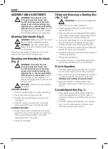
ASSEMBLY AND ADJUSTMENTS
WARNING: To reduce the risk
of serious personal injury, turn
tool off and disconnect tool from
power source before making any
adjustments or removing/installing
attachments or accessories.
Be sure
the trigger switch is in the OFF position.
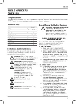
Attaching Side Handle (Fig. 2)
WARNING:
Before using the tool, check
WARNING:
The side handle should
always be used to maintain control of the
Mounting and Removing the Guard
(Fig. 3)
WARNING: To reduce the risk
of serious personal injury, turn
tool off and disconnect tool from
power source before making any
adjustments or removing/installing
attachments or accessories.
Before
reconnecting the tool, depress and
release the trigger switch to ensure that
CAUTION:
Guards must be used with
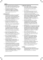
TO MOUNT THE GUARD
2. Press the guard (C) down (Fig. 3A).
3. Position the guard between your body and
4. Tight the screw (L) holding the cinch collar
firmly around the neck of spindle (Fig. 3B)
TO REMOVE THE GUARD
1. Loosen the screw (L) holding the cinch collar
the screw remains attached to the collar.
remain attached to the collar.
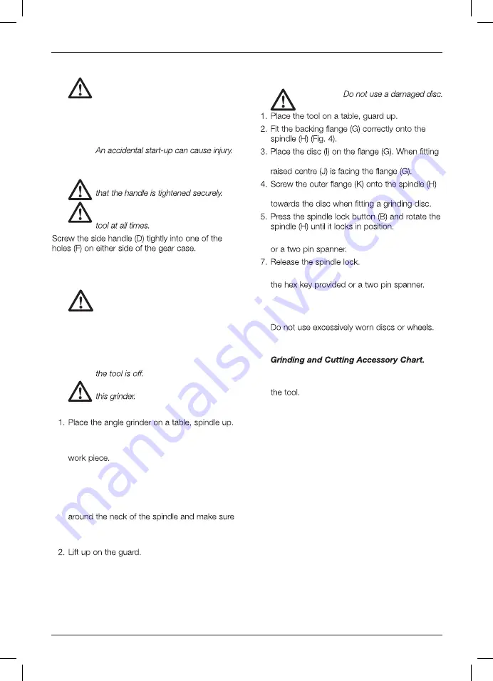
Fitting and Removing a Grinding Disc
(Fig. 1, 4, 5)
WARNING:
a disc with a raised centre, make sure that the
(Fig. 5). The ring on the flange (K) must face
6. Tighten the flange (K) with the hex key provided
8. To remove the disc, loosen the flange (K) with
Prior to Operation
• Install the guard and appropriate disc or wheel.
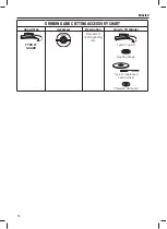
• Be sure the inner and outer flange are mounted
correctly. Follow the instructions given in the
• Make sure the disc or wheel rotates in the
direction of the arrows on the accessory and
Variable Speed Dial (Fig. 1)
• The variable speed dial (M) offers added tool
control and enables the tool to be used at
optimum conditions to suit the accessory and
material.
Turn the variable speed dial (M) to the desired
level. Turn the dial upward for higher speed
and downward for lower speed.
•
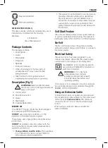
Summary of Contents for DWE4119
Page 1: ...DWE4119 ...
Page 2: ...English 5 original instructions ...
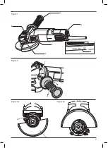
Page 3: ...3 A D E D F C E B D A C M L 2 ...
Page 4: ...4 H G K J I K I H G ...
Page 15: ......
Page 16: ...N855938 05 2020 ...