background image

English

4

Never start the tool with a person in line with the 
wheel.

 This includes the operator.

s ) 

Use of accessories not specified in this manual 
is not recommended and may be hazardous. 

Use of power boosters that would cause the tool 
to be driven at speeds greater than its rated speed 
constitutes misuse.

t ) 

Use clamps or another practical way to secure 
and support the workpiece to a stable platform. 

Holding the work by hand or against your body leaves 
it unstable and may lead to loss of control.

u ) 

Avoid bouncing the wheel or giving it rough 
treatment.

 If this occurs, stop the tool and inspect the 

wheel for cracks or flaws.

v )  Always handle and store wheels in a careful manner.
w ) 

Do not operate this tool for long periods of time. 
Vibration caused by the operating action of this 
tool may cause permanent injury to fingers, 
hands, and arms.

 Use gloves to provide extra 

cushion, take frequent rest periods, and limit daily 
time of use.

x ) 

Air vents often cover moving parts and should be 
avoided.

 Loose clothes, jewelry or long hair can be 

caught in moving parts.

Causes and Operator Prevention  
of Kickback

Kickback is a sudden reaction to a pinched or snagged 
rotating wheel, backing pad, brush or any other accessory. 
Pinching or snagging causes rapid stalling of the rotating 
accessory which in turn causes the uncontrolled power tool to 
be forced in the direction opposite of the accessory’s rotation 
at the point of the binding.
For example, if an abrasive wheel is snagged or pinched by 
the workpiece, the edge of the wheel that is entering into the 
pinch point can dig into the surface of the material causing 
the wheel to climb out or kick out. The wheel may either jump 
toward or away from the operator, depending on direction 
of the wheel’s movement at the point of pinching. Abrasive 
wheels may also break under these conditions.
Kickback is the result of tool misuse and/or incorrect operating 
procedures or conditions and can be avoided by taking proper 
precautions as given below:

a ) 

Maintain a firm grip on the power tool and 
position your body and arm to allow you to resist 
kickback forces. Always use auxiliary handle, if 
provided, for maximum control over kickback or 
torque reaction during start up. 

The operator can 

control torque reaction or kickback forces, if proper 
precautions are taken.

b ) 

Never place your hand near the rotating 
accessory. 

Accessory may kickback over your hand.

c ) 

Do not position your body in the area where 
power tool will move if kickback occurs.

 Kickback 

will propel the tool in direction opposite to the wheel’s 
movement at the point of snagging.

d ) 

Use special care when working corners, sharp 
edges etc. Avoid bouncing and snagging the 
accessory. 

Corners, sharp edges or bouncing have 

a tendency to snag the rotating accessory and cause 
loss of control or kickback.

e ) 

Do not attach a saw chain woodcarving blade 
or toothed saw blade. 

Such blades create frequent 

kickback and loss of control.

Safety Warnings Specific for Grinding and 
Abrasive Cutting-Off Operations

a ) 

Use only wheel types that are recommended for 
your power tool and the specific guard designed 
for the selected wheel. 

Wheels for which the power 

tool was not designed cannot be adequately guarded 
and are unsafe.

b ) 

The grinding surface of center depressed 
wheels must be mounted below the plane of 
the guard lip.

 An improperly mounted wheel that 

projects through the plane of the guard lip cannot be 
adequately protected.

c ) 

The guard must be securely attached to the 
power tool and positioned for maximum safety, 
so the least amount of wheel is exposed towards 
the operator. 

The guard helps to protect the operator 

from broken wheel fragments, accidental contact with 
wheel and sparks that could ignite clothing.

d ) 

Wheels must be used only for recommended 
applications. For example: do not grind with the 
side of cut-off wheel. 

Abrasive cut-off wheels are 

intended for peripheral grinding, side forces applied to 
these wheels may cause them to shatter.

e ) 

Always use undamaged wheel flanges that 
are of correct size and shape for your selected 
wheel. Proper wheel flanges support the wheel 
thus reducing the possibility of wheel breakage.


Flanges for cut-off wheels may be different from 
grinding wheel flanges.

f ) 

Do not use worn down wheels from larger power 
tools. 

Wheel intended for larger power tool is not 

suitable for the higher speed of a smaller tool and 
may burst.

Additional Safety Warnings Specific for 
Abrasive Cutting-Off Operations

a ) 

Do not “jam” the cut-off wheel or apply excessive 
pressure. Do not attempt to make an excessive 
depth of cut. 

Overstressing the wheel increases the 

loading and susceptibility to twisting or binding of 
the wheel in the cut and the possibility of kickback or 
wheel breakage.

b ) 

Do not position your body in line with and 
behind the rotating wheel. 

When the wheel, at the 

point of operation, is moving away from your body, 
the possible kickback may propel the spinning wheel 
and the power tool directly at you.

Summary of Contents for DWE46144N

Page 1: ...on ou tout commentaire nous contacter Si tiene dudas o comentarios contáctenos 1 800 4 DeWALT Instruction Manual Guide D utilisation Manual de instrucciones DWE46144N DWE46166N Cut Off Tools Outils de tronçonnage Herramientas de corte final page size 8 5 x 5 5 in ...

Page 2: ...English English original instructions 1 Français traduction de la notice d instructions originale 15 Español traducido de las instrucciones originales 31 ...

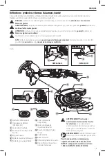
Page 3: ... a practice not related to personal injury which if not avoided may result in property damage WARNING Read all safety warnings and all instructions Failure to follow the warnings and instructions may result in electric shock fire and or serious injury WARNING To reduce the risk of injury read the instruction manual If you have any questions or comments about this or any DeWALT tool call us toll fr...

Page 4: ...t such as dust mask non skid safety shoes hard hat or hearing protection used for appropriate conditions will reduce personal injuries c Prevent unintentional starting Ensure the switch is in the off position before connecting to power source and or battery pack picking up or carrying the tool Carrying power tools with your finger on the switch or energizing power tools that have the switch on inv...

Page 5: ...ive equipment Depending on application use face shield safety goggles or safety glasses As appropriate wear dust mask hearing protectors gloves and workshop apron capable of stopping small abrasive or workpiece fragments The eye protection must be capable of stopping flying debris generated by various operations The dust mask or respirator must be capable of filtrating particles generated by your ...

Page 6: ...kickback over your hand c Do not position your body in the area where power tool will move if kickback occurs Kickback will propel the tool in direction opposite to the wheel s movement at the point of snagging d Use special care when working corners sharp edges etc Avoid bouncing and snagging the accessory Corners sharp edges or bouncing have a tendency to snag the rotating accessory and cause lo...

Page 7: ...0 15 2 m of the use of this product Additional Safety Information WARNING ALWAYS use safety glasses Everyday eyeglasses are NOT safety glasses Also use face or dust mask if cutting operation is dusty ALWAYS WEAR CERTIFIED SAFETY EQUIPMENT ANSI Z87 1 eye protection CAN CSA Z94 3 ANSI S12 6 S3 19 hearing protection NIOSH OSHA MSHA respiratory protection WARNING Some dust created by power sanding saw...

Page 8: ...s appropriate for this tool type and rated for at least 12 0 lbs 5 43 Kg Crush cut or entanglement hazard Do not use near moving parts mechanisms or running machinery Do not anchor the tool lanyard to anything on your body Anchor to a rigid structure that can withstand the forces of a dropped tool Make sure the lanyard is properly secure at each end prior to use Inspect tool and lanyard before eac...

Page 9: ...f still being held on and then re engaged to restart tool The tool will power off each time the current load reaches the overload current value motor burn up point If continued overload shutdowns occur apply less force weight on the tool until the tool will function without the overload engaging Electronic Soft Start This feature limits the initial start up momentum allowing the speed to build up ...

Page 10: ...sure proper installation with spring return function by depressing guard release lever 15 Mounting Guard Fig D CAUTION Prior to mounting guard ensure the screw lever and spring are fitted correctly before mounting the guard 1 With the spindle facing the operator press and hold the guard release lever 15 2 Align the lugs 12 on the guard with the slots 18 on the gear case cover 3 Push the guard down...

Page 11: ...ond coated cutting wheels WARNING Use of a damaged flange or guard or fail ure to use proper flange and guard can re sult in injury due to wheel breakage and wheel contact See the Accessories Chart for more information 1 Place the tool on a table guard up 2 Install the unthreaded backing flange 6 on spindle 19 with the raised center pilot facing the wheel NOTE The 3 76 mm diameter stamped steel ba...

Page 12: ...es or wheels provided with a threaded hub These accessories are available at extra cost from your local dealer or authorised service center 1 Place the tool on a table guard up 2 Thread the wheel on the spindle by hand 3 Depress spindle lock button 4 and use a wrench on the hub of the wire wheel or brush to tighten the wheel 4 To remove the wheel reverse the above procedure NOTICE To reduce the ri...

Page 13: ...h 2 The tool will run while the switch is depressed 2 Turn the tool off by releasing the paddle switch Spindle Lock Fig A The spindle lock 4 is provided to prevent the spindle from rotating when installing or removing wheels Operate the spindle lock only when the tool is turned off unplugged from the power supply and has come to a complete stop NOTICE To reduce the risk of damage to the tool do no...

Page 14: ... Cleaning and Disposal 1 All surfaces in the work area should be vacuumed and thoroughly cleaned daily for the duration of the sanding project Vacuum filter bags should be changed frequently 2 Plastic drop cloths should be gathered up and disposed of along with any dust chips or other removal debris They should be placed in sealed refuse receptacles and disposed of through regular trash pick up pr...

Page 15: ...lacement parts Register Online Thank you for your purchase Register your product now for WARRANTY SERVICE Registering your product will help you obtain more efficient warranty service in case there is a problem with your product CONFIRMATION OF OWNERSHIP In case of an insurance loss such as fire flood or theft your registration of ownership will serve as your proof of purchase FOR YOUR SAFETY Regi...

Page 16: ... threaded locking flange OR Type 1 41 guard unthreaded backing flange diamond cutting wheel threaded locking flange Wire Wheels Type 27 guard 3 4 76 2 102 mm wire cup brush Type 27 guard 4 6 100 150 mm wire wheel Sanding Discs rubber backing pad sanding disc sanding clamp nut ACCESSORIES CHART Type 1 41 guards are intended for use with Type 1 41 cutting wheels and Type 27 wheels marked for cutting...

Page 17: ...en n est fait pour l éviter pourrait poser des risques de dommages matériels AVERTISSEMENT lire tous les avertissements de sécurité et toutes les directives Le non respect des avertissements et des directives pourrait se solder par un choc électrique un incendie et ou une blessure grave AVERTISSEMENT afin de réduire le risque de blessures lire le mode d emploi de l outil Pour toute question ou rem...

Page 18: ...l est impossible d éviter l utilisation d un outil électrique dans un endroit humide brancher l outil dans une prise ou sur un circuit d alimentation dotés d un disjoncteur de fuite à la terre GFCI L utilisation de ce type de disjoncteur réduit les risques de choc électrique 3 Sécurité personnelle a Être vigilant surveiller le travail effectué et faire preuve de jugement lorsqu un outil électrique...

Page 19: ...et outil ou qui n aurait pas reçu une approbation spécifique du fabricant de l outil En effet il est parfois possible de fixer un accessoire à l outil électrique toutefois cela ne garantit pas une utilisation sécuritaire c Le régime nominal de l accessoire doit être au moins égal au régime maximal inscrit sur l outil électrique Les accessoires soumis à un régime plus élevé que celui pour lequel il...

Page 20: ...dans ce manuel n est pas recommandée et peut être dangereuse L utilisation de compresseurs pour faire fonctionner l outil à une vitesse supérieure à sa vitesse nominale est prohibée t Utiliser des serre joints ou tout autre moyen pour fixer et soutenir le matériau sur une surface stable Tenir la pièce à la main ou contre son corps offre une stabilité insuffisante qui pourrait vous en faire perdre ...

Page 21: ...eules à ponçage f Ne pas utiliser de meule usée en provenance d outil de dimension plus importante Ces meules prévues pour un outil électrique plus grand ne conviennent pas au régime plus élevé d un outil de plus petite dimension et pourraient éclater Avertissements de sécurité supplémentaires spécifiques aux opérations de coupe par abrasion a Ne pas coincer la meule tronçonneuse ou ne pas appliqu...

Page 22: ...ux Pour réduire toute exposition à ces produits travailler dans un endroit bien aéré en utilisant du matériel de sécurité homologué tel un masque antipoussières spécialement conçu pour filtrer les particules microscopiques Limiter toute exposition prolongée avec les poussières provenant du ponçage sciage meulage perçage ou toute autre activité de construction Porter des vêtements de protection et ...

Page 23: ...rrectement amarré à chaque extrémité avant chaque utilisation Vérifier le bon état et fonctionnement de l outil et du cordage d amarrage avant chaque utilisation y compris tout tissu et point de suture Ne pas utiliser en cas de dommages ou de dysfonctionnement Ne pas altérer le dispositif de connexion du cordage d amarrage ou l utiliser autrement que comme indiqué dans ce guide d utilisation N att...

Page 24: ... courant ou de toute autre coupure accidentelle l interrupteur devra être relâché le cas échéant puis réenclenché pour redémarrer l outil E ClutchMC Cet outil est équipé d un E ClutchMC embrayage électronique qui en cas de surcharge ou de grippage de meule éteint automatiquement l outil pour réduire l impact physique de tout retour de couple sur l utilisateur L interrupteur devra être relâché le c...

Page 25: ...r l option désirée 1 Retirez la vis 16 à l aide d un embout T20 2 Retirez le levier de déverrouillage du carter en prenant note de la position du ressort Choisissez l extrémité du levier correspondant à l option de réglage désirée Le mode One touch utilise l extrémité oblique du levier 15 pour s encastrer dans les orifices d alignement 13 du collier de serrage du carter Le mode Two touch utilisera...

Page 26: ...avant de retirer ou installer toute pièce ou tout accessoire Installation de meules sans moyeu Fig G H AVERTISSEMENT toute installation incorrecte de bride et ou meule pose des risques de dommages corporels et matériels graves outil ou meule ATTENTION les brides incluses avec l outil doivent être utilisées avec les meules à moyeu déporté de type 27 42 et les meules à tronçonner de types 1 41 Se re...

Page 27: ...brasive et l écrou de blocage soient bien resserrés 5 Pour retirer la meule attrapez et tournez le tampon de soutien et le tampon ponceur tout en poussant sur le bouton de verrouillage de la broche Fig I 23 22 21 Installation et retrait des meules à moyeu Fig A Les meules à moyeu s installent directement sur la broche Le filetage des accessoires doit correspondre à celui de la broche 1 Retirez la ...

Page 28: ...rancher avant d effectuer tout réglage et d enlever ou d installer tout accessoire Un démarrage accidentel peut provoquer des blessures Position correcte des mains Fig J AVERTISSEMENT pour réduire tout risque de dommages corporels graves adopter SYSTÉMATIQUEMENT la position des mains illustrée AVERTISSEMENT pour réduire tout risque de dommages corporels graves maintenir SYSTÉMATIQUEMENT l outil fe...

Page 29: ...l et la surface de travail Reportez vous à la partie du tableau correspondant à la fonction particulière Fonction Angle Meulage 20 30 Ponçage avec disques à lamelles 5 10 Ponçage avec tampon de soutien 5 15 Brossage métallique 5 10 4 Maintenez le contact entre le bord de la meule et la surface de travail Lors du meulage ou du ponçage avec des disques à lamelles ou des brosses métalliques déplacez ...

Page 30: ...ythme de meulage coupe est supérieur lorsque l outil fonctionne à grande vitesse 3 Placez vous de façon à ce que la face inférieure de la meule soit à votre opposé 4 Ne changez pas l angle de coupe une fois que cette dernière est commencée et qu une entaille existe dans la pièce à travailler Cela pourrait faire arquer la meule et la casser Les meules angulaires ne sont pas conçues pour supporter u...

Page 31: ... l usage abusif de l outil Pour obtenir de plus amples renseignements sur les pièces ou les réparations couvertes par la présente garantie visiter le site www dewalt com ou composer le 1 800 433 9258 1 800 4 DeWALT Cette garantie ne s applique pas aux accessoires et ne vise pas les dommages causés par des réparations effectuées par un tiers Cette garantie confère des droits légaux particuliers à l...

Page 32: ...possible qui ne rentrera pas en contact avec l accessoire Disques de ponçage à lamelles de 115 mm 4 5 po et 150 mm 6 po Carter de type 27 Bride de soutien non filetée Disque de ponçage à lamelles sans moyeu Bride de verrouillage taraudée Carter de type 27 Disque de ponçage à lamelles et moyeu REMARQUE des carters de type 27 sont vendus séparément chez votre distributeur local ou dans les centres d...

Page 33: ...xterno 12 Orejetas del protector 13 Orificio de alineamiento del protector 14 Conexión del cordón Definiciones Símbolos y palabras de alerta de seguridad Este manual de instrucciones utiliza los siguientes símbolos y palabras de alerta de seguridad para alertarle de situaciones peligrosas y del riesgo de lesiones corporales o daños materiales PELIGRO Indica una situación de peligro inminente que s...

Page 34: ...húmedo es imposible de evitar utilice un suministro protegido con un interruptor de circuito por falla a tierra GFCI El uso de un GFCI reduce el riesgo de descargas eléctricas 3 Seguridad Personal a Permanezca alerta controle lo que está haciendo y utilice el sentido común cuando emplee una herramienta eléctrica No utilice una herramienta eléctrica si está cansado o bajo el efecto de drogas alcoho...

Page 35: ...provistas con esta herramienta eléctrica El incumplimiento de todas las instrucciones enumeradas a continuación puede provocar una descarga eléctrica un incendio o lesiones graves b No utilice accesorios que no estén diseñados y recomendados específicamente por el fabricante de la herramienta El hecho que el accesorio pueda conectarse a la herramienta eléctrica no garantiza un funcionamiento segur...

Page 36: ...detectados Nunca encienda la herramienta si una persona está parada frente al disco Esta instrucción incluye al operador s El uso de accesorios no especificados en este manual no se recomienda y puede ser peligroso El uso de amplificadores de potencia que hagan que la herramienta funcione a velocidades mayores que su velocidad nominal constituye un mal uso t Use abrazaderas u otra forma práctica d...

Page 37: ... esmerilado f No utilice discos desgastados de herramientas eléctricas más grandes Los discos diseñados para herramientas eléctricas más grandes no son apropiados para la mayor velocidad de una herramienta más pequeña y pueden estallar Advertencias de seguridad adicionales específicas para operaciones de corte abrasivo a No atasque el disco de corte ni aplique una presión excesiva No intente reali...

Page 38: ...robados como mascarillas antipolvo especialmente diseñadas para filtrar partículas microscópicas Evite el contacto prolongado con polvo generado por el lijado aserrado pulido taladrado y otras actividades de construcción Vista ropas protectoras y lave las áreas de la piel expuestas con agua y jabón Si permite que el polvo se introduzca en la boca u ojos o quede sobre la piel puede favorecer la abs...

Page 39: ... herramienta a nada en su cuerpo Sujételo a una estructura rígida que pueda soportar las fuerzas de una herramienta que se caiga Asegúrese de que el cordón esté bien sujeto a cada extremo antes de utilizarlo Inspeccione la herramienta y el cordón antes de cada uso para determinar si se han producido daños y si funcionan correctamente incluida la tela y las costuras No los utilice si están dañados ...

Page 40: ... reparada antes de volver a utilizarse Protección E switch El interruptor de gatillo de encendido apagado tiene una función de desconexión por falta de corriente En caso de interrupción del suministro eléctrico u otro apagado inesperado el interruptor tendrá que liberarse si está encendido y volver a activarse para arrancar de nuevo la herramienta E Clutch Esta unidad está equipada con un E Clutch...

Page 41: ...io o antihorario con el eje mirando al usuario Fijación de las opciones de ajuste del protector Para ajustar la palanca de liberación del protector 15 para la opción de ajuste deseada 1 Retire el tornillo 16 utilizando una broca T20 2 Retire la palanca de liberación del protector tomando nota de la posición del resorte Elija el extremo de la palanca para la opción de ajuste deseada One touch utili...

Page 42: ...los tornillos hasta un par de 18 pulg lbs 2 03 Nm Si se aprietan demasiado la rosca puede desgastarse 5 Vuelva a instalar el protector y corrija las bridas para los accesorios apropiados Bridas y discos ATENCIÓN Apague y desenchufe la herramienta antes de realizar ajustes o de extraer o instalar accesorios Montaje de discos sin cubo Fig G H ADVERTENCIA El no fijar adecuadamente las bridas y o el d...

Page 43: ...el disco de lijado y la almohadilla de respaldo 4 Apriete a mano la tuerca de fijación Luego presione el botón del seguro del eje mientras gira el disco de lijado hasta que éste y la tuerca de fijación estén bien ajustados 5 Para retirar el disco agarre y gire la almohadilla de respaldo y la almohadilla de lijado mientras presiona el botón de seguro del eje Fig I 23 22 21 Montaje y retiro de los d...

Page 44: ...cción de las flechas en el accesorio y la herramienta OPERACIÓN ADVERTENCIA Para reducir el riesgo de lesiones personales graves apague la herramienta y desconéctela de la fuente de alimentación antes de realizar ajustes o de retirar instalar dispositivos o accesorios Un arranque accidental podría causar lesiones Posición adecuada de las manos Fig J ADVERTENCIA Para reducir el riesgo de lesión per...

Page 45: ...nce la velocidad máxima antes de ponerla en contacto con la superficie de trabajo 2 Aplique una presión mínima a la superficie de trabajo permitiendo a la herramienta operar a alta velocidad La velocidad de eliminación de material es mayor cuando la herramienta opera a velocidad alta Angle Fig L 3 Mantenga un ángulo apropiado entre la herramienta y la superficie de trabajo Consulte la tabla de acu...

Page 46: ...disco es nuevo Reduzca la profundidad de corte muesca equivalente a la reducción del radio del disco a medida que se desgaste Consulte la Cuadro de Accesorios si desea más información El esmerilado corte de bordes con un disco tipo 41 requiere el uso de un protector tipo 1 1 Permita que la herramienta alcance la velocidad máxima antes de ponerla en contacto con la superficie de trabajo 2 Aplique u...

Page 47: ... QRO Av San Roque 274 Col San Gregorio 442 2 17 63 14 SAN LUIS POTOSI SLP Av Universidad 1525 Col San Luis 444 814 2383 TORREON COAH Blvd Independencia 96 Pte Col Centro 871 716 5265 VERACRUZ VER Prolongación Díaz Mirón 4280 Col Remes 229 921 7016 VILLAHERMOSA TAB Constitución 516 A Col Centro 993 312 5111 PARA OTRAS LOCALIDADES Si se encuentra en México por favor llame al 55 5326 7100 Si se encue...

Page 48: ...as herramientas DeWALT están cubiertas por 1 AÑO DE SERVICIO GRATUITO DeWALT mantendrá la herramienta y reemplazará las piezas gastadas por su uso normal sin cobro en cualquier momento durante un año a contar de la fecha de compra Los artículos gastados por la clavadora tales como la unidad de hoja y retorno del impulsador no están cubiertas GARANTÍA DE REEMBOLSO DE SU DINERO POR 90 DÍAS Si no est...

Page 49: ...de corte tipo 1 41 y discos tipo 27 marcados solamente para cortar Esmerilar con discos que no sean del tipo 27 y del tipo 29 requiere distintos protectores de accesorios Utilice siempre el protector apropiado más pequeño posible que no esté en contacto con el accesorio NOTA Un protector de tipo 27 puede obtenerse por un costo adicional en su proveedor local o centro de servicio autorizado NOTA Un...

Page 50: ......

Page 51: ......

Page 52: ...44N DWE46166N Copyright 2018 DeWALT The following are trademarks for one or more DeWALT power tools the yellow and black color scheme the D shaped air intake grill the array of pyramids on the handgrip the kit box configuration and the array of lozenge shaped humps on the surface of the tool ...

Reviews: