background image

7

English

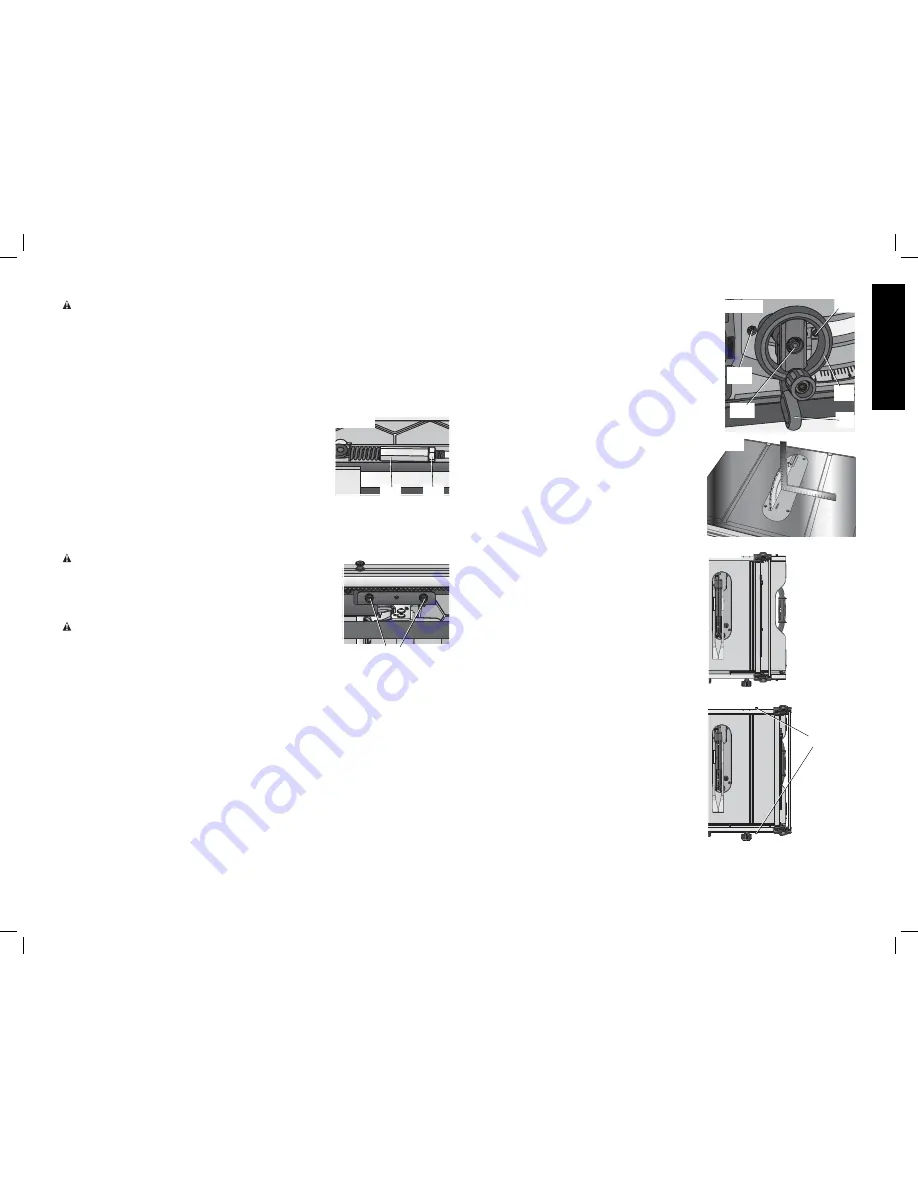
BEVEL STOP AND POINTER ADJUSTMENT (FIG. 19, 20)

 1. Raise the blade fully by rotating the blade height 

adjustment wheel (F) clockwise until it stops.

  2. Unlock the bevel lock lever (G) by pushing it up and to 

the right. Loosen the bevel stop screw (NN).

  3. Place a square flat against the table top and against the 

blade between teeth, as shown in Figure 20. Ensure the 
bevel lock lever is in its unlocked, or up, position.

  4. Using the bevel lock lever, adjust the bevel angle until it 

is flat against the square.

  5. Tighten the bevel lock lever by pushing it down.
  6. Turn the bevel stop cam (MM) until it firmly contacts the 

bearing block. Tighten the bevel stop screw (NN).

  7. Check the bevel angle scale. If the pointer does not 

read 0°, loosen pointer screw (OO) and move the 
pointer so it reads correctly. Retighten the pointer 
screw.

  8. Repeat at 45°, but do not adjust pointer.

MITER GAUGE ADJUSTMENT (FIG. 2)

To adjust miter gauge (J) loosen knob, set to desired 
angle and tighten knob.

FENCE ALIGNMENT ADJUSTMENT (FIG. 2, 21)
(Blade Parallel to Fence)

If you experience fence alignment problems and want 
to correct an out of parallel alignment between the 
fence and the blade, be sure to check the alignment 
of the blade to the miter slot first. After confirming that 
those elements are aligned, proceed with alignment of 
the blade to the fence using the following procedure:

POSITION 1 FENCE ALIGNMENT (FIG. 21)

  1. Install the fence in position 1 (Fig. 21) and unlock 

the rail lock lever (E). Locate both locator pins (DD) 
that support the fence on the front and rear rails.

  2. Loosen the rear locator pin screw and adjust the 

allignment of the fence in the groove until the 
fence face is parallel to the blade. Make sure you 
measure from the fence face to the front and back 
of the blade to ensure alignment.

  3. Tighten the locator pin screw and repeat on the 

left side of the blade.

  4. Check rip scale pointer adjustment.

POSITION 2 FENCE ALIGNMENT
(FIG. 22, 23)

 1. To align position 2 fence locator pins, ensure 

position 1 pins have been aligned, refer to 

Position 

1 Fence Alignment

.

  2. Loosen the position 2 locator pins, then using the 

blade wrench holes as a guide for positioning, 
align the pins (Fig. 23).

  3. Tighten the locator pins (front and rear).

FIG. 19

G

OO

F

NN

MM

FIG. 20

FIG. 21

POSITION 1

POSITION 2

FIG. 22

DD

ADJUSTMENTS

WARNING: To reduce the risk of injury, turn unit off and disconnect machine from 

power source

 before installing and removing accessories, before adjusting or changing set-

ups or when making repairs. An accidental start-up can cause injury.

NOTE:

 This saw is fully and accurately adjusted at the factory at the time of manufacture. If 

readjustment due to shipping and handling or any other reason is required, follow the sections 
below to adjust this saw.
Once made, these adjustments should remain accurate. Take a little time now to follow these 
directions carefully to maintain the accuracy of which this saw is capable.

RAIL LOCK ADJUSTMENT (FIG. 2, 17)
(Tightening Fence Clamping System)

  1. Lock the rail lock lever (E).
  2. On the underside of the saw, loosen the jam nut (JJ).
 3. Tighten the hex rod (KK) until the spring on the locking 

system is compressed creating the desired tension on the 
rail lock lever. Retighten the jam nut against the hex rod.

  4. Check that the fence does not move when the lock lever is 

engaged. If the fence is still loose, tighten the spring further.

RIP SCALE ADJUSTMENT

See 

Adjusting the Rip Scale

 under 

Assembly

.

BLADE ALIGNMENT ADJUSTMENT (FIG. 18)
(Blade Parallel to Miter Slot)

WARNING:

 Cut Hazard. Check the blade at 0˚ and 45˚ to 

make sure blade does not hit the throat plate, causing personal 
injury.

If the blade appears to be out of alignment with the miter slot on 
the table top, it will require calibration for alignment. To realign the 
blade and miter slot, use the following procedure:

WARNING: To reduce the risk of injury, turn unit off and 

disconnect machine from power source

 before installing and 

removing accessories, before adjusting or changing set-ups or 
when making repairs. An accidental start-up can cause injury.

  1. Using a 6 mm hex wrench, loosen rear pivot bracket fasteners (LL) just enough to allow 

the bracket to move side-to-side.

  2. Adjust the bracket until the blade is parallel to the miter gauge slot.
  3. Tighten the rear pivot bracket fasteners to 110–120 in-lbs (12.5–13.6 Nm).

FIG. 17

KK

JJ

FIG. 18

LL

Summary of Contents for DWE7499

Page 1: ... PÓLIZA DE GARANTÍA ADVERTENCIA LÉASE ESTE INSTRUCTIVO ANTES DE USAR EL PRODUCTO Before returning this product call 1 800 4 DEWALT IF YOU SHOULD EXPERIENCE A PROBLEM WITH YOUR DEWALT PURCHASE CALL 1 800 4 DEWALT IN MOST CASES A DEWALT REPRESENTATIVE CAN RESOLVE YOUR PROBLEM OVER THE PHONE IF YOU HAVE A SUGGESTION OR COMMENT GIVE US A CALL YOUR FEEDBACK IS VITAL TO THE SUCCESS OF DEWALT S QUALITY I...

Page 2: ... and adjusting wrenches are removed from spindle before turning tool on Tools scrap pieces and other debris can be thrown at high speed causing injury KEEP WORK AREA CLEAN Cluttered areas and benches invite accidents DO NOT USE THE MACHINE IN A DANGEROUS ENVIRONMENT The use of power tools in damp or wet locations or in rain can cause shock or electrocution Keep your work area well lit to avoid tri...

Page 3: ...rmation is also available from the National Safety Council 1121 Spring Lake Drive Itasca IL 60143 3201 Please refer to the U S Department of Labor OSHA 1910 213 Regulations metal prongs when unplugging or plugging in the cord An accidental start up can cause injury REDUCE THE RISK OF UNINTENTIONAL STARTING Make sure that the switch is in the OFF position before plugging in the power cord In the ev...

Page 4: ...MANUAL AND YOU SHOULD BECOME FAMILIAR WITH THEM Thru sawing refers to any cut that completely cuts through the workpiece Non thru sawing refers to any cut that does not completely cut through the workpiece Push Stick refers to a wooden or plastic stick usually homemade that is used to push small workpiece through the saw and keeps the operator s hands clear of the blade Kickback occurs when the sa...

Page 5: ...able saw is completely assembled and you have read the entire instruction manual Open the box and slide the saw out as shown in Figure 1 Carefully unpack the table saw and all loose items from the carton Examine all parts to make sure that parts have not been damaged during shipping If any parts are missing or damaged contact your dealer to replace them before attempting to assemble the tool FEATU...

Page 6: ...The throat plate includes four adjustment screws which raise or lower the throat plate When properly adjusted the front of the throat plate should be flush or slightly below the surface of the table top and secured in place The rear of the throat plate should be flush or slightly above the table top ASSEMBLY WARNING Shock Hazard To reduce the risk of serious personal injury turn unit off and disco...

Page 7: ...10 percent or more will cause a loss of power and overheating All DEWALT tools are factory tested If this tool does not operate check the power supply TO REMOVE THE THROAT PLATE 1 Remove the throat plate Q by turning the cam lock knob CC 1 4 turn counterclockwise 2 Using finger hole DD on the plate pull throat plate up and forward to expose the inside of the saw DO NOT operate the saw without the ...

Page 8: ...osition 2 locator pins then using the blade wrench holes as a guide for positioning align the pins Fig 23 3 Tighten the locator pins front and rear FIG 19 G OO F NN MM FIG 20 FIG 21 POSITION 1 POSITION 2 FIG 22 DD ADJUSTMENTS WARNING To reduce the risk of injury turn unit off and disconnect machine from power source before installing and removing accessories before adjusting or changing set ups or...

Page 9: ...width marked on the blade or on the blade packaging The splitter and riving knife thickness must be greater than the body thickness and less than the kerf width as shown in Figure 26 RIVING KNIFE THICKNESS KERF WIDTH WIDTH OF CUT MADE BY THE BLADE BODY OR PLATE THICKNESS OF THE BLADE FIG 26 FIG 23 DD U ALIGNING RIVING KNIFE TO BLADE FIG 24 1 Remove the throat plate Refer to Remove Throat Plate und...

Page 10: ...ll times to reduce the risk of a thrown workpiece and possible injury There are two basic types of cutting with table saws ripping and crosscutting Regardless of material man made or natural wood the distinction between ripping and crosscutting is as follows Ripping is cutting to a different width usually with the grain and crosscutting describes cutting material across the shorter dimension usual...

Page 11: ...is tilted away from the fence and hands WARNING Keep hands clear of the blade On Off Switch Fig 29 WARNING To reduce the risk of injury be sure the switch is in the OFF position before plugging machine in Pull the red paddle H to turn this saw on and push down the red paddle to turn the saw off LOCK OFF FEATURE INSTRUCTIONS To lock the saw off insert a padlock underneath the paddle A padlock with ...

Page 12: ... or slightly lower than the saw table CAUTION Never push or hold onto the free or cut off side of the workpiece if it is between the blade and the fence Ripping Small Pieces Fig 34 It is unsafe to rip small pieces It is not safe to put your hands close to the blade Instead rip a larger piece to obtain the desired piece When a small width is to be ripped and the hand cannot be safely put between th...

Page 13: ...mly against the miter gauge with the path of the blade in line with the desired cut location Keep the workpiece an inch or so in front of the blade KEEP BOTH HANDS AWAY FROM THE BLADE AND THE PATH OF THE BLADE Fig 39 FIG 39 4 Start the saw motor and allow the blade to come up to speed 5 While using both hands to keep the workpiece against the face of the miter gauge and holding the workpiece flat ...

Page 14: ...lade guard assembly not touching the blade before starting the motor CAUTION Certain workpiece shapes such as molding may not lift the blade guard assembly properly Feed the workpiece slowly to start the cut If the blade guard assembly contacts the blade place the workpiece under the blade guard assembly not touching the blade before starting the motor This operation is the same as crosscutting ex...

Page 15: ...ication Fig 44 1 All motor bearings are permanently lubricated at the factory and no additional lubrication is needed 2 The height adjustment screw may require periodic cleaning and lubrication If you have difficulty raising or lowering the blade a Unplug the saw b Turn the saw on its side so the bottom open part of the unit is accessible c Clean and lubricate the height adjustment screw threads Z...

Page 16: ... and replacement should be performed by a DEWALT factory service center a DEWALT authorized service center or other qualified service personnel Always use identical replacement parts Register Online Thank you for your purchase Register your product now for WARRANTY SERVICE Registering your product will help you obtain more efficient warranty service in case there is a problem with your product CON...

Page 17: ...ouper ATENCIÓN fabrique varas de empuje de madera contrachapada o madera blanda cuyo ancho sea igual o menor que el ancho del material que desea cortar Push Stick Pattern Modèle de poussoir Patrón de la vara de empuje Adjust length of push stick so hand will clear blade guard and rip fence Régler la longueur du poussoir de sorte que la main sera dégagée du protège lame et du guide longitudinal Aju...

Reviews: