background image

6

English

FEATURES

SPraY GUn BoDY

The body of the spray gun is designed to be well-balanced 

and lightweight. The body is a compact size and has a fine 

spray for precision jobs. 
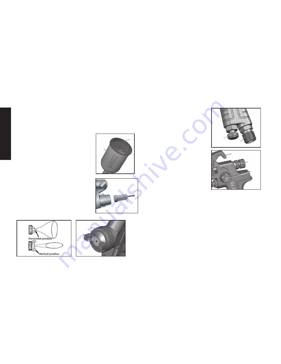
SPraY GUn cUP

The 

cup (a) of the spray gun can hold 

133 mL (4.5 oz) and has a removable 

snap in

 lid (K). The design of the spray 

gun cup 

lid (K) includes a lip around the 

edge of the lid for easy removal from the 

spray gun cup (a).
MaTerIal FIlTer 
The 

material filter (B) is used to protect 

against contaminants and small par-

ticles.It is located inside of the spray gun, 

between the 

spray gun cup (a) and air 

cap (c).
aIr caP hornS

The position of the 

air cap (c) horns (D) 

allow two spray patterns.  

See Fig. 2.

aIr VolUMe conTrol KnoB

The 

air volume control knob (F) 

controls the air flow and allows for 

a MAX of 30 PSI to reduce over-

spray and efficient air consumption. 
aIr InleT 

The tool’s

 air inlet (G) located at 

the bottom of the handle is used 

for connecting an air supply that 

has a standard 1/4” NPT  

American thread.
FlUID conTrol KnoB

The 

fluid control knob (I) allows 

control of the material amount  

released (the density of the  

“fan spray”).
PaTTern conTrol KnoB

The 

pattern control knob (h) allows 

the width of the “fan spray”  

to be adjusted.
FIXeD hooK

The spray gun includes a 

fixed hook (J) on the body to allow for 

convenient hanging when stored. 

H

I

J

D

C

F

G

K

A

B

Summary of Contents for DWMT70778

Page 1: ...DWMT70778 Gravity Feed Touch Up Spray Gun s ...

Page 2: ...RN LENGTH 3 5 90MM MIN WORKING PRESSURE 30PSI MAX WORKING PRESSURE 60PSI AVERAGE AIR CONSUMPTION 50PSI 4 1 SCFM 2 0 L s 1 4 CFM 0 67 L s NET WEIGHT 0 75 LBS 0 34Kg AIR INTLET SIZE 1 4 NPS M RECOMMENDED HOSE SIZE 3 8 10MM DWMT70778 GRAVITY FEED TOUCH UP SPRAY GUN G Air Inlet H Pattern Control Knob I Fluid Control Knob J Hook K Spray Gun Cup Lid L Air Valve Nut FIG 1 A B C D E F G H I J K L FIG 2 ...

Page 3: ...ONS WARNING This product contains chemicals known to the State of California to cause cancer and birth defects or other reproductive harm Wash hands after handling SAVE THESE INSTRUCTIONS WARNING Improper operation or maintenance of this product could result in serious injury and property damage Read and understand all warnings and operating instructions before using this equipment When using air ...

Page 4: ...All persons in the work area must always wear approved eye and hearing protection and approved respiratory protection when this spray gun is in operation Never aim spray gun at anyone Do not spray near sparks open flame lit cigarettes pilot lights space heaters or any other potential ignition source DO NOT SMOKE IN WORK AREA Only persons well acquainted with these rules of safe operation should be...

Page 5: ...mputation or other serious injury See a physician immediately Never place hands in front of nozzle Direct spray away from self and others Seek immediate medical attention if direct spray contacts exposed body parts WARNING RISK from flying objects What can happen How to prevent it Certain parts are under pressure whenever the gun is connected to a pressurized air line These parts may be propelled ...

Page 6: ...cup A and air cap C AIR CAP HORNS The position of the air cap C horns D allow two spray patterns See Fig 2 AIR VOLUME CONTROL KNOB The air volume control knob F controls the air flow and allows for a MAX of 30 PSI to reduce over spray and efficient air consumption aIR INLET The tool s air inlet G located at the bottom of the handle is used for connecting an air supply that has a standard 1 4 NPT A...

Page 7: ...ine lubricators and air line filters is recommended to prevent water in the line that can damage the tool Drain the air tank daily Clean the air inlet filter screen on at least a weekly schedule to remove accumulated dirt or other matter that can restrict air flow The tool s air inlet used for connecting an air supply has standard 1 4 NPT American thread Safety Rules For Pneumatic Tools 1 Inspect ...

Page 8: ...may result in serious injury 4 Adjust air pressure on the air compressor CAUTION DO NOT exceed 60 PSI 5 Depress the spray gun trigger E fully to spray material NOTE Depressing the trigger partially will cause only air to be released ADJUST SPRAY GUN 1 Turn the fluid control knob I counterclockwise to increase the amount of material released or clockwise to decrease 2 Turn the pattern control knob ...

Page 9: ... clean clogged holes The smallest amount of damage may cause irregular spray pattern NOTE If the fluid nozzle is to be removed for thorough cleaning squeeze the trigger to prevent damage of the fluid needle tip when unscrewing the nozzle Lubrication Lubrication procedures must be observed after thoroughly cleaning the gun to ensure effective high quality performance of spray gun 1 Lubricate workin...

Page 10: ...d Remedy 1 Fluid nozzle cracked or worn 2 Leak at thread of fluid nozzle 3 Leak at fluid needle 4 Needle packing worn out 5 Insufficient fluid in cup 6 Vent hole in container cover clogged 1 Tighten or replace 2 Tighten fluid nozzle 3 Tighten compression nut assembly or replace needle packing 4 Replace packing 5 Fill cup with fluid 6 Clean out Air back pressuring into cup Excessive air blowing bac...

Page 11: ...logged side Soak side ports in thinner to clean clog DO NOT poke any opening with hard objects B 1 Dried material at fluid nozzle C restricts air flow 2 Loose air nozzle 3 Air pressure set too high 1 Remove air nozzle Wipe off fluid tip using a cloth soaked in thinner or by soft brush 2 Fasten nozzle securely 3 Reduce air pressure TROUBLESHOOTING GUIDE This section provides a list of the more freq...

Reviews: