background image

7

INSTALLATION

Air Supply

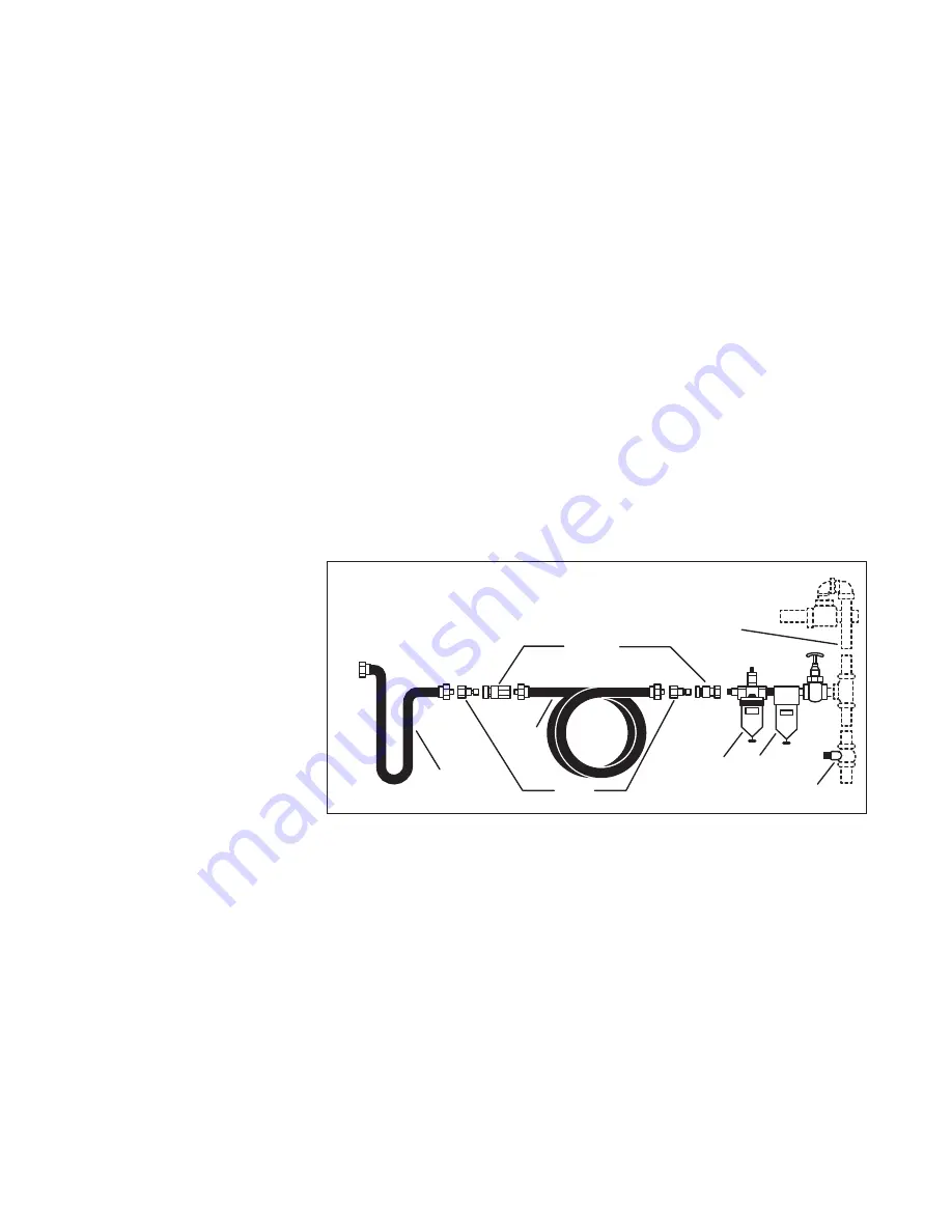
The recommended hook-up is shown in 

Figure a. Pneumatic tools 

operate on a wide range of air pressures. For maximum efficiency 

and longer tool life, the pressure of the air supplied to these 

tools 

MUST not exceed the rated PSI at the tool when the tool is 

running. Using a higher than rated pressure will cause faster wear 

and drastically shorten the tool’s life. A higher air pressure can also 

cause an unsafe condition and explosion.

The inside diameter of the hose 

should be increased to compensate for 

unusually long air hoses (over 25 feet).  

Minimum hose diameter should be 3/8” 

I.D. and fittings should

have 1/4” NPT thread.

The use of air line lubricators and air 

line filters is recommended to prevent 

water in the line that can damage the 

tool. Drain the air tank daily. Clean the 

air inlet filter screen on at least a weekly 

schedule to remove accumulated dirt or 

other matter that can restrict air flow.

The tool’s air inlet used for connecting 

an air supply has standard 1/4” NPT  

American thread. 

Safety Rules For Pneumatic Tools

1) Inspect the air hose for cracks or other problems.

Replace the hose if worn.

2) Never point an air hose at another person.

3) Disconnect the tool when not in use, or before performing

service or changing accessories.

4) Use proper hoses and fittings. Never use quick change

couplings attached to the tool. Instead, add a hose and

coupling between the tool and the air supply.

1/2”(or larger) 

Pipe and Fittings

Coupler

Air Hose

Leader Hose

Tool

Nipple

Oiler

Filter

Drain Daily

Figure A

Summary of Contents for DWMT70778

Page 1: ...DWMT70778 Gravity Feed Touch Up Spray Gun s ...

Page 2: ...RN LENGTH 3 5 90MM MIN WORKING PRESSURE 30PSI MAX WORKING PRESSURE 60PSI AVERAGE AIR CONSUMPTION 50PSI 4 1 SCFM 2 0 L s 1 4 CFM 0 67 L s NET WEIGHT 0 75 LBS 0 34Kg AIR INTLET SIZE 1 4 NPS M RECOMMENDED HOSE SIZE 3 8 10MM DWMT70778 GRAVITY FEED TOUCH UP SPRAY GUN G Air Inlet H Pattern Control Knob I Fluid Control Knob J Hook K Spray Gun Cup Lid L Air Valve Nut FIG 1 A B C D E F G H I J K L FIG 2 ...

Page 3: ...ONS WARNING This product contains chemicals known to the State of California to cause cancer and birth defects or other reproductive harm Wash hands after handling SAVE THESE INSTRUCTIONS WARNING Improper operation or maintenance of this product could result in serious injury and property damage Read and understand all warnings and operating instructions before using this equipment When using air ...

Page 4: ...All persons in the work area must always wear approved eye and hearing protection and approved respiratory protection when this spray gun is in operation Never aim spray gun at anyone Do not spray near sparks open flame lit cigarettes pilot lights space heaters or any other potential ignition source DO NOT SMOKE IN WORK AREA Only persons well acquainted with these rules of safe operation should be...

Page 5: ...mputation or other serious injury See a physician immediately Never place hands in front of nozzle Direct spray away from self and others Seek immediate medical attention if direct spray contacts exposed body parts WARNING RISK from flying objects What can happen How to prevent it Certain parts are under pressure whenever the gun is connected to a pressurized air line These parts may be propelled ...

Page 6: ...cup A and air cap C AIR CAP HORNS The position of the air cap C horns D allow two spray patterns See Fig 2 AIR VOLUME CONTROL KNOB The air volume control knob F controls the air flow and allows for a MAX of 30 PSI to reduce over spray and efficient air consumption aIR INLET The tool s air inlet G located at the bottom of the handle is used for connecting an air supply that has a standard 1 4 NPT A...

Page 7: ...ine lubricators and air line filters is recommended to prevent water in the line that can damage the tool Drain the air tank daily Clean the air inlet filter screen on at least a weekly schedule to remove accumulated dirt or other matter that can restrict air flow The tool s air inlet used for connecting an air supply has standard 1 4 NPT American thread Safety Rules For Pneumatic Tools 1 Inspect ...

Page 8: ...may result in serious injury 4 Adjust air pressure on the air compressor CAUTION DO NOT exceed 60 PSI 5 Depress the spray gun trigger E fully to spray material NOTE Depressing the trigger partially will cause only air to be released ADJUST SPRAY GUN 1 Turn the fluid control knob I counterclockwise to increase the amount of material released or clockwise to decrease 2 Turn the pattern control knob ...

Page 9: ... clean clogged holes The smallest amount of damage may cause irregular spray pattern NOTE If the fluid nozzle is to be removed for thorough cleaning squeeze the trigger to prevent damage of the fluid needle tip when unscrewing the nozzle Lubrication Lubrication procedures must be observed after thoroughly cleaning the gun to ensure effective high quality performance of spray gun 1 Lubricate workin...

Page 10: ...d Remedy 1 Fluid nozzle cracked or worn 2 Leak at thread of fluid nozzle 3 Leak at fluid needle 4 Needle packing worn out 5 Insufficient fluid in cup 6 Vent hole in container cover clogged 1 Tighten or replace 2 Tighten fluid nozzle 3 Tighten compression nut assembly or replace needle packing 4 Replace packing 5 Fill cup with fluid 6 Clean out Air back pressuring into cup Excessive air blowing bac...

Page 11: ...logged side Soak side ports in thinner to clean clog DO NOT poke any opening with hard objects B 1 Dried material at fluid nozzle C restricts air flow 2 Loose air nozzle 3 Air pressure set too high 1 Remove air nozzle Wipe off fluid tip using a cloth soaked in thinner or by soft brush 2 Fasten nozzle securely 3 Reduce air pressure TROUBLESHOOTING GUIDE This section provides a list of the more freq...

Reviews: