
DXCM019-0352
Filter/Regulator/Lubricator, 3/8” NPT
IF YOU HAVE ANY QUESTIONS OR COMMENTS ABOUT THIS OR ANY DEWALT TOOL, CALL
US TOLL FREE AT: 1-888-895-4549.
WARNING:
For your own safety, read the air compressor instruction manual before using any
accessory. Failure to heed these warnings may result in personal injury and serious damage to the
air compressor and the accessory. When servicing this tool, use only identical replacement parts.
WARNING: CONTAINS LEAD.
May be harmful if eaten or chewed. May generate dust
containing lead. Wash hands after use. Keep out of reach of children.
WARNING:
This product can expose you to chemicals including Lead and Cadmium, which are
known to the State of California to cause cancer and birth defects or other reproductive harm. For
more information go to www.P65Warnings.ca.gov.
WARNING:
This product is specifically designed for compressed air service ONLY.
TYPICAL INSTALLATION
WARNING:
ALWAYS turn compressor OFF, disconnect from power source, and drain all
pressure from system before servicing.
Note:
Air supply must be dry enough to avoid ice formation at temperatures below 35°F (2°C).
Note:
These products are designed specifically for compressed air service only.
Note:
Use a thread sealer or Teflon® tape on all male threads.
CAUTION:
Do not install filter or lubricator to a system where the compressor is lubricated with,
or the air contains, a material that will attack plastic bowls. Certain compressor oils, household
cleaners, chemicals, solvents, paints, or fumes can cause plastic bowl failure.
FILTER/REGULATOR/LUBRICATOR
Maximum inlet pressure: 220 psig (15 bar)
Pressure range: 5-150 psig (0,3 to 10 bar)
Maximum operating temperature: 150°F (65°C)
INSTALLATION
1. Install as close as possible to where regulated air is needed. In systems with a cyclic demand,
locate upstream of cycling device.
Note:
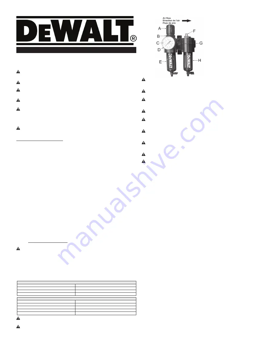
Air flow must be in same direction as arrow on
regulator body.
Note:
Securing to a wall using the attached mounting brackets will provide added stability
and rigidity to your piping system.
2. System piping should be 3/8” minimum. Avoid using fittings, couplings, etc., that restrict the
flow of air.
3. Install gauge (C) in front regulator port (FIG. 1).
4. Turn filter and regulator bowls (E & H) fully clockwise into body before pressurizing.
OPERATION OF FILTER/REGULATOR
1.
Pull adjustment knob (A) out to unlock,
turn counter clockwise until it stops (closed position).
2. Check that all connections are tight. A small leak will substantially reduce the performance
of your compressor. If you suspect a leak, spray a small amount of soapy water around the area
with a spray bottle. If bubbles appear, retighten or reseal the connection. Do not overtighten.
3. Turn regulator adjustment knob clockwise until the desired outlet pressure is reached, as
indicated on gauge.
Note:
To avoid minor readjustments after making a change in pressure setting, always approach
the desired pressure from a lower setting. When reducing from a higher to a lower setting, first
reduce to a lesser pressure, then go up to the desired setting.
4. When the required pressure is reached, push in adjustment knob to lock setting.
Note:
Drain filter bowl (E) whenever water can be seen in bowl by turning the manual drain valve.
OPERATION OF LUBRICATOR
Oil Reservoir Size: 2.2 fluid oz. (65ml)
1. The Lubricator (H) cannot be filled under pressure. Verify air is shut off and relieve all system
pressure. Remove and fill bowl with air tool oil. An SAE 10 or lighter oil will also be sufficient.
Note: REFILL RESERVOIR WITH OIL.
Shut off inlet pressure and reduce pressure in reservoir
to zero. Remove fill plug, add oil and reinstall fill plug.
WARNING:
Do not remove the fill plug when the reservoir is pressurized, as oil will blow out
the fill plug.
2. Reinstall lubricator bowl (H) securely (hand tighten) before pressurizing system.
3. Turn on system pressure.
4. Adjust lubricator drip rate only when there is a constant rate of air flow thru the lubricator.
Monitor drip rate thru sight feed dome (F).
5. Turn the slotted rotator in sight feed dome (F) to obtain the recommended drops per minute.
(
See Drip Rate Chart
.) Turn rotator counterclockwise to increase and clockwise to decrease the
drip rate. (Total rotator travel is 2 full turns.)
6. Monitor the tool being lubricated for a few days and adjust the drip rate of the oil delivery.
DRIP RATE CHART
Flow - scfm (dm³/s)
Drops per minute
2 to 5 (0,9 to 2,4)
7
5 to 30 (2,4 to 14,2)
8
30 to 40 (14,2 to 18,9)
9
SPECIFICATIONS
Maximum inlet Pressure
220 psi
Max. Temperature
150°F (65°C)
Air Inlet/outlet
3/8” NPT (F)
Regulator style
Self relieving
Minimum flow rate
78 SCFM @ 90 psi
WARNING:
ALWAYS turn compressor OFF, disconnect from power source, and drain all
pressure from system before servicing. Personal injury and/or property damage could occur.
WARNING:
RISK OF ELECTRIC SHOCK, FIRE, AND/OR INJURY.
Keep the work area clean
and well lighted. Cluttered benches and dark areas increase the risks of electric shock, fire, and
injury to persons. Place cleaning rags and other flammable waste materials in a secured metal
container. The container should be disposed of properly in accordance with local, state, and fed-
eral regulations.
FIG. 1
WARNING:
RISK OF EXPLOSION AND/OR FIRE.
Do not operate the tool in explosive atmo-
spheres, such as in the presence of flammable liquids, gases, or dust. The tool is able to create
sparks resulting in the ignition of the dust or fumes.
WARNING:
RISK OF INJURY.
Keep bystanders, children, and visitors away while operating
the tool. Distractions are able to result in the loss of control of the tool.
WARNING:
RISK OF INJURY.
Dress properly. Do not wear loose clothing or jewelry. Contain
long hair. Keep hair, clothing, and gloves away from moving parts. Loose clothes, jewelry, or long
hair increase the risk of injury to persons as a result of being caught in moving parts.
WARNING:
RISK OF HEARING LOSS.
Always wear ANSI S3.19 approved ear protection
when using the tool. Prolonged exposure to high intensity noise is able to cause hearing loss.
WARNING:
RISK OF EYE INJURY.
Always wear ANSI Z87.1 approved safety goggles when
using an air tool. Air powered equipment and power tools are capable of propelling materials such
as metal chips, sawdust, and other debris at high speed which could result in serious eye injury.
WARNING:
RISK OF INJURY.
Disconnect the tool from the air supply when not in use. NEVER
change accessories or perform maintenance or service operations while the tool is connected to
the air supply.
WARNING:
RISK OF BURSTING AND/OR INJURY.
Check for damaged air hose. Keep the
air hose away from heat, oil, and sharp edges. Inspect the air hose periodically and replace it if it
becomes worn or damaged.
WARNING:
RISK OF INJURY.
Tool service must be performed only by qualified repair per-
sonnel.
WARNING:
RISK OF INJURY.
When servicing a tool, use only identical replacement parts.
Use only authorized parts.
Use only the lubricants supplied with the tool or specified by the manufacturer.
WARRANTY
ONE YEAR LIMITED WARRANTY:
DEWALT Industrial Tools (the Company) warrants that for a
period of twelve (12) months from the date of purchase, it will replace or repair, free of charge,
for the original retail purchaser only, any part or parts, manufactured by the Company, found
upon examination by the Company or its assigned representatives, to be defective in material
or workmanship or both. All transportation charges for parts submitted for replacement or repair
under this warranty must be borne by the original retail purchaser. This is the exclusive remedy
under this warranty.
Failure by the original retail purchaser to install, maintain and operate said equipment in accor-
dance with good industry practices, or failure to comply with the specific recommendations of the
Company set forth in the owner’s manual, shall render this warranty null and void. The Company
shall not be liable for any repairs, replacements, or adjustments to the equipment or any costs for
labor performed by the purchaser without the Company’s prior written approval. The effects of cor-
rosion, erosion and normal wear and tear are specifically excluded from this warranty.
THE COMPANY MAKES NO OTHER WARRANTY OR REPRESENTATION OF ANY KIND
WHATSOEVER, EXPRESSED OR IMPLIED EXCEPT THAT OF TITLE. ALL IMPLIED
WARRANTIES, INCLUDING ANY WARRANTY OF MERCHANTABILITY AND FITNESS FOR
PARTICULAR PURPOSE ARE HEREBY DISCLAIMED. LIABILITY FOR CONSEQUENTIAL
AND INCIDENTAL DAMAGES UNDER ANY AND ALL WARRANTIES, OTHER CONTRACTS,
NEGLIGENCE, OR OTHER SORTS IS EXCLUDED TO THE EXTENT EXCLUSION IS PERMITTED
BY LAW.
Notwithstanding the above, any legal claim against the Company shall be barred if legal action
thereon is not commenced within twenty-four (24) months from the date of purchase or delivery
whichever occurs last. This warranty constitutes the entire agreement between the Company and
the original retail purchaser and no representative or agent is authorized to alter the terms of same
without expressed written consent of the Company.
ENGLISH
COMPONENTS
A. Adjustment knob
B. Regulator
C. Gauge
D. Inlet
E. Filter bowl
F. Sight feed dome
G. Outlet
H. Lubricator bowl


