19
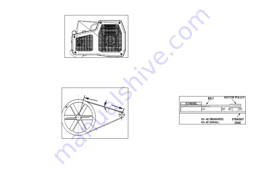
2. Remove the belt guard by
X
removing the 5 screws
(X) using a Phillips head
screwdriver.
3. Mark pump position on
saddle.
4. Loosen
the
motor
mounting screws and
slide the motor toward
the air compressor.
5. Remove the belt and replace with a new one.
6. See the
Adjusting Belt Tension
before tightening motor
mounting screws.
Adjusting Belt Tension
1. Slide motor into original position, line the motor up with the
mark made earlier on saddle.
2. Tighten two outside
Downwar
d Force
Deflection
motor
mounting
screws enough to hold
the motor in place for
checking pulley and
flywheel alignment.
3. The belt should deflect
1/2” (13 mm)at mid
-
way between the pul
-
ley and the flywheel
when a 5 pound
(2.26 kg.) weight is
applied at the midway
point.
4. When proper belt tension is achieved, tighten
all four motor mounting screws. Torque to 20-25 ft-lbs
(27.1–33.9 Nm).
NOTE:
Once the engine pulley has been moved from its factory set
location, the grooves of the flywheel and pulley must be aligned
to within 1/16” (1.6 mm) to prevent excessive belt wear. Verify the
alignment by performing the following
Motor Pulley/Flywheel -
Alignment.
Motor Pulley/Flywheel Alignment
NOTE:
Once the motor pulley has been moved from its factory set
location, the grooves of the flywheel and pulley must be aligned to
within 1/16” (1.6 mm) to prevent excessive belt wear.
The air compressor flywheel and motor pulley must be in-line (in the
same plane) within 1/16” (1.6 mm) to assure belt retention within
flywheel belt grooves. To check alignment, perform the following
steps:
1. Set the Auto/Off lever to “Off”, unplug the unit, and relieve all
air pressure from the air tank.
2. Remove belt guard.
3. Place a straightedge
against the outside of
the flywheel and the
motor drive pulley.
4. Measure the distance
between the edge of
the belt and the straightedge at points A1 and A2 in figure.
The difference between measurements should be no more than
1/16” (1.6 mm).
5. If the difference is greater than 1/16” (1.6 mm) loosen the set
screw holding the motor drive pulley to the shaft and adjust
the pulley’s position on the shaft until the A1 and A2 measure
-


