Section 2 Direct Excitation (Brush Type)
16
Diagnostic Repair Manual
Procedure
1.
Set DMM to measure Resistance.
2.
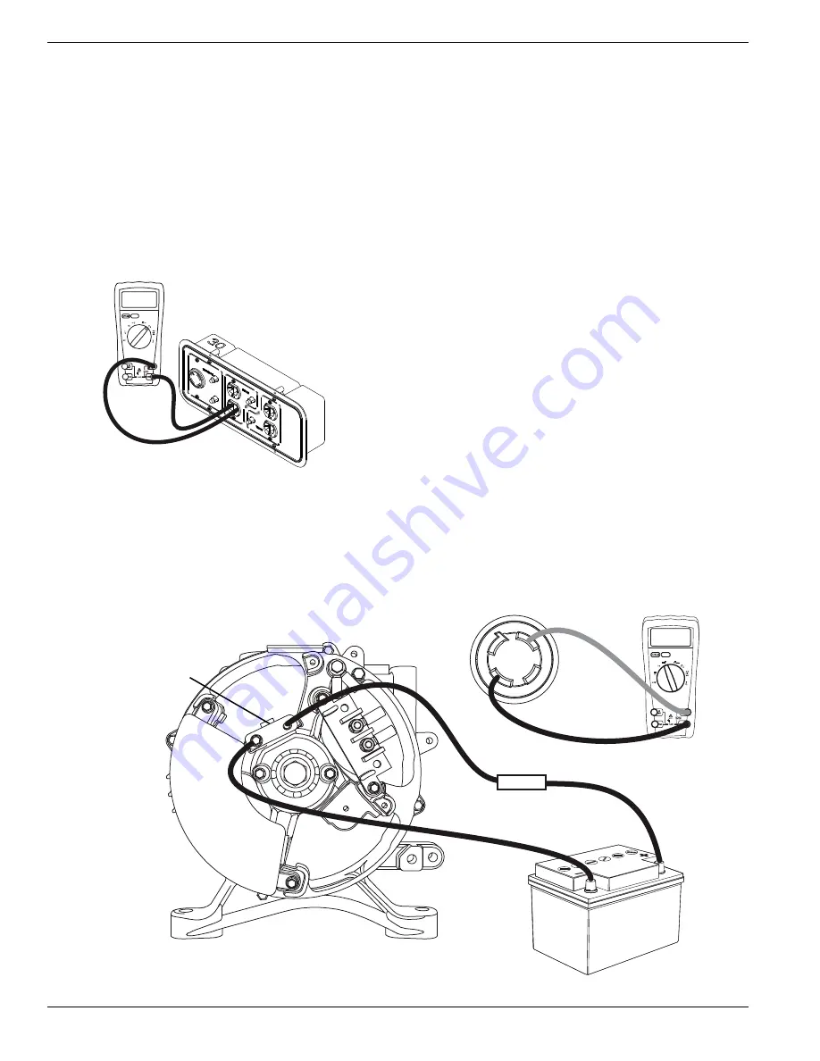
See
. Connect DMM to each receptacle
on unit.
NOTE:
Only one outlet on each receptacle needs to be
tested.
Results
1.
If any other reading than continuity was measured,
further troubleshooting needs to be done to
determine if it is the receptacle or the wiring.
2.
If receptacles test good, refer to flow chart.
Figure 1-7. Checking Continuity of Receptacles
Test 4 – Fixed Excitation Test/Rotor
Amp Draw Test
General Theory
Supplying a fixed DC current to the rotor will induce a
magnetic field in the rotor. With the generator running,
this should create a proportional voltage output from the
stator windings.
NOTE:
A standard 12 Volt battery is needed for this
procedure.
NOTE:
Always use the unit specific schematics and
wiring diagrams for brush orientation.
Procedure
1.
Remove positive and negative wires connected to
the brush assembly.
2.
Connect one jumper wire to where the positive
brush wire was connected to on the brush
assembly.
3.
Connect another jumper wire to where the negative
brush wire was connected to on the brush
assembly.
NOTE:
For safety, install an in-line fuse in the positive
jumper wire. Maximum fuse should be 2 amps.
4.
Set DMM to measure AC Voltage.
5.
See
. Connect meter test leads across
the 240 VAC receptacle so the leads read line-to-
line voltage.
6.
Set RUN-STOP switch to RUN and start unit.
Figure 2-8. Jumper Wires Between Battery and Brush Assembly
0.01 Ohms
!62
6/,4
"!44%29
6!#
2%#%04!#,%
6!#
&53%
"253(!33%-",9
003973


