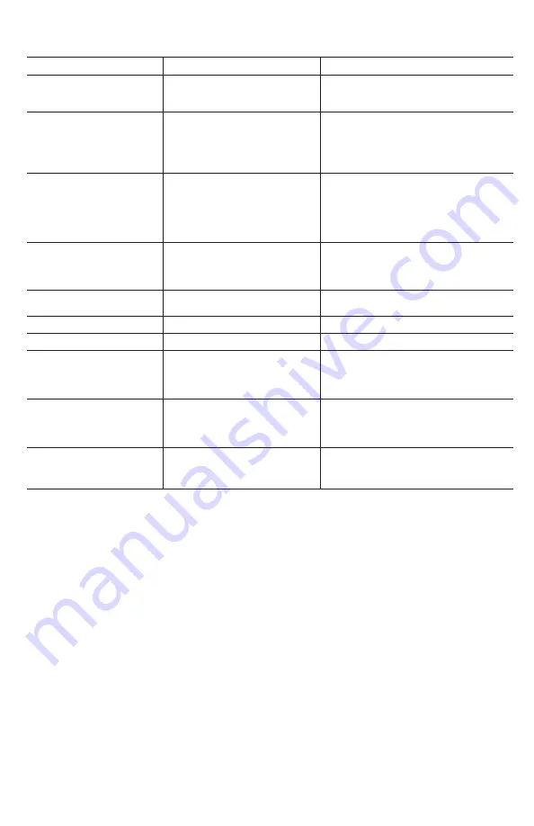
background image

7

ENGLISH

PROBLEM

CAUSE

SOLUTION

Sprayer starts to spray when pumping 

or sprayer will not stop spraying when 

shut-off lever is released.

Shut-off lock is engaged.  

Squeeze shut-off lever and disengage the lock.                     

See 

Pressurizing and Spraying

 section

.

Sprayer will not build pressure.

1.    Pressure  chamber  installed  into  pump.                                    
            

2.  Dirty, damaged or worn pump or chamber    

o

   o-ring.                                                       

3.  Dirty poppet in pump.

1.  Install pressure chamber as described in 

Pressure         

C

  Chamber Maintenance

 section.

2.  Clean and lubricate or replace o-rings as described in 


  Seal Servicing

 section.                                                           

3.  Clean sprayer as described in 

Cleaning

 section.  

Sprayer will not spray.

1.  Sprayer pressurization.

2.  Shut-off clogged.

3.  Nozzle clogged.

1.  Pressurize sprayer as described in 

Pressurizing


and


S

   Spraying

 section.

2.  Clean shut-off as described in 

Shut-off Maintenance 

s


section.

3.  Clean nozzle as described in 

Nozzle Maintenance       

s

   section.

Sprayer leaks from the bottom of 

the tank.

1.  Loose pump nut.

2.  Damaged or worn o-rings or seals.   

1. Tighten pump nut as described in 

Seal Servicing


se

Section.

2.  Replace o-rings and seals as described in 

Seal     

Se

Servicing

 section.

Sprayer leaks where piston rod enters 

top of the tank.

Dirty, damaged, or worn grommet.

   Clean and lubricate hole in grommet or replace              

g

 grommet as described in 

Seal Servicing

 section.

Hose leaks at tank connection.

Cracked, swollen or faulty hose.

Replace shut-off assembly.

Hose leaks at shut-off.

Cracked, swollen or faulty hose.

Replace shut-off assembly.

Pump handle is difficult to operate.

1.  Swollen or damaged pump piston o-ring.

2.  Dirty, dry or damaged grommet.

1. Clean and lubricate or replace o-ring as described in     

S


Seal Servicing

 section.

2. Clean and lubricate hole in grommet or replace                

g

  grommet as described in 

Seal Servicing

 section.

Nozzle drips when shut-off lever is 

released.

1.  Dirt or debris in shut-off valve.

2.  Damaged o-ring or seal in shut-off.

1.  Clean shut-off as described in 

Shut-off Maintenance


s

   section.

2.  Service shut-off seals as described in 

Shut-off                

 Maintenance

 section.

Nozzle tip leaks, poor spray pattern, 

partial spray or complete stoppage.

1.  Flat seal is missing or damaged.
2.  Spray extension or nozzle clogged.

1.  Replace flat seal at extension tip.
2.  Remove nozzle and clean as described in 

Nozzle                    

M

 Maintenance

 section.

TROUBLESHOOTING

© 2020 DEWALT
DEWALT® and GUARANTEED TOUGH® are registered trademarks of
the DEWALT Industrial Tool Co., used under license. All rights reserved.
The yellow and black color scheme is a trademark for DEWALT
Power Tools and Accessories.

Made in China
Manufactured under license and distributed by:
The Fountainhead Group, Inc.
23 Garden Street
New York Mills, NY 13417 U.S.A.
Fax: (315) 768-4220
Email: Info@TheFGI.com
www.TheFountainheadGroup.com

Three Year Limited Warranty

The warranty of this product is covered by:                                                                 

The Fountainhead Group, Inc. (800)-311-9903
We warrant that each product sold by us will be free from defects in material 

and workmanship for a period of three years from the date of shipment by us. 

We make no other express warranties, and all implied warranties, including 

fitness and merchantability, are limited to three years from the date of shipment 

by us. Within the warranty period, we will repair or replace any part found to 

be defective upon our examination but will not pay shipping cost or other 

expenses. To obtain warranty service, contact us at: The Fountainhead Group, 

Inc., c/o Customer Service, 23 Garden Street, New York Mills, New York 13417, 

or call prepaid, Area Code (800) 311-9903 or (315) 736- 0037. Merchandise may 

not be returned without prior permission and must be returned to us prepaid. 

This warranty service is an exclusive remedy and we are not responsible for 

any consequential or incidental damages or injury to person(s) or property. 

This warranty shall not apply to any product which has been subject to misuse, 

negligence or accident, or been damaged in shipment, or misapplied, or which 

has been modified or repaired by unauthorized persons. This warranty only 

applies to products owned by persons purchasing directly from us or from our 

approved distributors and merchandisers. The right is reserved to incorporate 

subsequent design or parts changes after publication and without reissue of 

descriptive literature or catalogs. 
NOTE: Limitations on duration of implied warranty and/or consequential 

damages might not apply to you if your state does not permit them. This 

warranty gives you specific legal rights in addition to rights you may have under 

state law..

Summary of Contents for DXSP190652

Page 1: ... Internal Piston Pump Backpack Sprayer Pulvérisateur sac à dos avec Pompe à Piston Interne de 15L Rociador de mochila con bomba de pistón interno de 4 galones Instruction Manual Guide D utilisation Manual de instrucciones SAVE THESE INSTRUCTIONS FOR FUTURE USE CONSERVER CES CONSIGNES POUR UTILISATION ULTÉRIEURE GUARDE ESTAS INSTRUCCIONES PARA VOLVER A CONSULTAR EN EL FUTURO ...

Page 2: ...English original instructions 1 Español traducido de las instrucciones originales 9 Français traduction de la notice d instructions originale 16 ...

Page 3: ...struction manual uses the following safety alert symbols and words to alert you to hazardous situations and your risk of personal injury or property damage DANGER Indicates an imminently hazardous situation which if not avoided will result in death or serious injury WARNING Indicates a potentially hazardous situation which if not avoided could result in death or serious injury CAUTION Indicates a ...

Page 4: ...he entire instruction manual before using this sprayer Follow all instructions and precautions in the instruction manual when using this sprayer Read and follow all instructions and precautions on chemical manufacturer s label of chemicals used in this sprayer Use the appropriate Personal Protective Equipment PPE as recommended by the chemical manufacturer and or refer to the chemical Safety Data ...

Page 5: ... Replace the cap and tighten securely Never use hot water for cleaning Fig H Fig I ASSEMBLY Pump Handle Tools Required 13mm or Adjustable Wrench not supplied 1 Slide handle onto shaft and line up holes Thread bolt through handle and shaft and securely tighten Thread on lock nut and tighten using a 13mm or adjustable wrench Handle can be mounted on left or right depending on user preference Fig C F...

Page 6: ...ter basket gasket Fig K Make sure they do not show signs of wear and are operating properly Replace them as required 3 Clean any dirt or debris from the filter basket 4 Periodically check the straps for fraying Replace them as required Shut off Maintenance 1 Unscrew the hose nut 1 from the shut off assembly 3 2 Remove the hose with attached filter 2 from the shut off assembly 3 3 Clean any debris ...

Page 7: ...ndle to the furthest downward position Remove pump handle from sprayer Fig W 5 Disassemble carry handle by removing the 6 screws Fig X 6 Remove hitch pin and lift pivot clip off of the piston rod Fig Y 7 Pull upward to slide piston rod out of pump Fig Z 8 While holding onto the pump use an adjustable wrench to unthread pump nut from pump Remove nut hose and barb assembly Fig AA 9 Inspect both o ri...

Page 8: ...Fig W Harness Installation 1 For each side remove the small plastic clips from the two shoulder strap loops and thread each loop through the slots at the top of the carry handle Replace the clips through the loops and pull strap securing the two shoulder straps in place Fig JJ 2 To install lower end of the straps remove strap from top portion of buckles and place around the foot stand starting fro...

Page 9: ...tension or nozzle clogged 1 Replace flat seal at extension tip 2 Remove nozzle and clean as described in Nozzle M Maintenance section TROUBLESHOOTING 2020 DEWALT DEWALT and GUARANTEED TOUGH are registered trademarks of the DEWALT Industrial Tool Co used under license All rights reserved The yellow and black color scheme is a trademark for DEWALT Power Tools and Accessories Made in China Manufactur...

Page 10: ...English 8 THIS PAGE INTENTIONALLY LEFT BLANK ESTA PÁGINA SE HA DEJADO EN BLANCO INTENCIONALMENTE CETTE PAGE A INTENTIONNELLEMENT ÉTÉ LAISSÉE EN BLANC ...

Page 11: ...lesiones leves o moderadas Utilizado sin palabras indica un mensaje de seguridad relacionado AVISO Se refiere a una práctica no relacionada a lesiones corporales que de no evitarse puede resultar en daños a la propiedad ADVERTENCIA Lea todas las advertencias de seguridad y todas las instrucciones El no cumplir con seguir las advertencias y las instrucciones puede dar como resultado lesiones graves...

Page 12: ... presión cuando el atomizador no esté en uso y antes de hacer cualquier mantenimiento Nunca almacene las sustancias químicas en el atomizador Almacene o elimine cualquier sustancia química no utilizada siguiendo las instrucciones del fabricante debido al potencial daño al medioambiente a causa de un derrame o descarga y o consulte los criterios de eliminación indicados en la Ficha técnica de segur...

Page 13: ...sta que quede asegurada Nunca utilice agua caliente para limpiar Fig H Fig I ENSAMBLAJE Mango de la bomba Herramientas necesarias Llave de 13 mm o ajustable no provista 1 Deslice el mango hacia el eje y alinee los orificios Pase el tornillo a través del mango y el eje y ajuste firmemente Enrosque la tuerca de bloqueo y ajústela usando una llave de 13 mm o ajustable Se puede fijar el mango al lado ...

Page 14: ... de que no presenten señales de desgaste y que estén funcionando correctamente Reemplácelas si es necesario 3 Limpie cualquier suciedad o residuo de la canasta del filtro 4 Revise periódicamente las correas para ver si existe algún desgaste Reemplácelas si es necesario Mantenimiento del dispositivo de cierre 1 Desatornille la tuerca de la manguera 1 de la válvula de cierre 3 2 Retire la manguera c...

Page 15: ...e el mango de la bomba del atomizador Fig W 5 Desensamble el mango de transporte retirando los 6 tornillos Fig X 6 Retire la clavija de enganche y levante el clip de pivote que se encuentra en la varilla de pistón Fig Y 7 Jale hacia arriba para retirar la varilla de pistón fuera de la bomba Fig Z 8 Mientras sostiene la bomba utilice una llave ajustable para retirar la tuerca de la bomba fuera de l...

Page 16: ...nstalación del arnés 1 En ambos lados retire los pasadores de plástico de las dos correas para hombro y enrosque cada aro a través de los orificios ubicados en la parte superior del mango principal Coloque nuevamente los pasadores a través de los aros y jale la correa para asegurar las dos correas para hombros Fig JJ 2 Para instalar el extremo inferior de las correas retire la correa de la parte s...

Page 17: ...ierre tal como se describe en la sección Mantenimiento del dispositivo de cierre La punta de la boquilla gotea patrón de atomización débil atomización parcial u obstrucción completo 1 Falta el sello plano o está dañado 2 La extensión de aspersión o la boquilla están bloqueadas 1 Reemplace el sello plano en la punta de la extensión 2 Retire la boquilla y límpiela tal como se describe en la sección ...

Page 18: ...ait entraîner des blessures légères ou modérées Si utilisé sans aucun terme Indique un message propre à la sécurité AVIS indique une pratique ne posant aucun risque de dommages corporels mais qui par contre si rien n est fait pour l éviter pourrait poser des risques de dommages matériels 1 Réservoir 2 Poignée de pompe pivotante 3 Poignée de transport intégrée 4 Boyau ultra robuste renforcé de nylo...

Page 19: ... RISQUE DE BLESSURE ET OU DE DOMMAGE À LA PROPRIÉTÉ RÉSULTANT D UNE EXPOSITION AUX PRODUITS CHIMIQUES Bien lire et comprendre le mode d emploi en entier avant d utiliser ce pulvérisateur Suivre toutes les instructions et les précautions du mode d emploi lorsque vous utilisez ce pulvérisateur Lire et suivre toutes les instructions et les précautions du fabricant sur l étiquette des produits chimiqu...

Page 20: ...le bouchon et serrer solidement Ne jamais utiliser d eau chaude pour le nettoyage Fig H Fig I ASSEMBLAGE Poignée de la pompe Outils requis clé de 13mm ou clé anglaise non fournie 1 Glisser la poignée sur l arbre et aligner les trous Fileter le boulon sur la poignée et l arbre et serrer fermement Visser le boulon autofreinant et serrer à l aide d une clé de 13mm ou clé anglaise La poignée peut être...

Page 21: ...le boyau et le dispositif d arrêt 7 Retirer le bouchon et vider le contenu sur du gravier ou le sol nu 8 Répéter les étapes 4 à 7 jusqu à ce que le réservoir soit complètement propre Retirer la buse lorsque vous purgez le système de pompage Nettoyer la buse avant de la replacer Entreposage du pulvérisateur 1 Ne jamais entreposer le pulvérisateur lorsqu il est sous pression ou qu il contient du liq...

Page 22: ...pe 4 Abaisser la poignée de la pompe à la plus basse position possible Retirer la poignée de la pompe du pulvérisateur Fig W 5 Démonter la poignée de transport en retirant les 6 vis Fig X 6 Retirer l agrafe de la goupille d attelage et soulever la fermeture de pivot de la tige du piston Fig Y 7 Tirer vers le haut pour glisser la tige du piston hors de la pompe Fig Z 8 En tenant la pompe utiliser u...

Page 23: ...ig W Installation du harnais 1 Pour chaque côté retirer les petites clips en plastique des deux anneaux de bretelle et passer chaque anneau à travers les fentes de la partie supérieure de la poignée de transport Replacer les clips à travers les anneaux et tirer sur la courroie pour maintenir les deux bretelles en place Fig JJ 2 Pour installer la partie inférieure des bretelles retirer la courroie ...

Page 24: ...e la buse dégoutte la pulvérisation n est pas uniforme la pulvérisation n est que partielle ou aucune pulvérisation 1 Le joint plat est manquant ou endommagé 2 La tige d extension ou la buse est obstruée 1 Remplacer le joint plat au bout de la tige d extension 2 Retirer la buse et la nettoyer tel que décrit à la section Entretien de la buse DÉPANNAGE Manual No 184608 Rev B Date 09 11 20 ECN 20 011...

Reviews: