
9
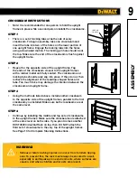
WARNING!
•
Serious or fatal crashing injuries can occur from furniture tipping
over. To prevent this, the rack must always be secured to a wall,
especially in earthquake-prone environments, where surfaces are
uneven, and where children and/or pets are present.
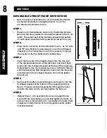
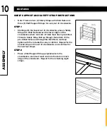
CROSSBEAM INSTRUCTIONS
•
Note: It is recommended for one person to hold the upright
frames in place while a second person installs the crossbeams.
STEP 1
•
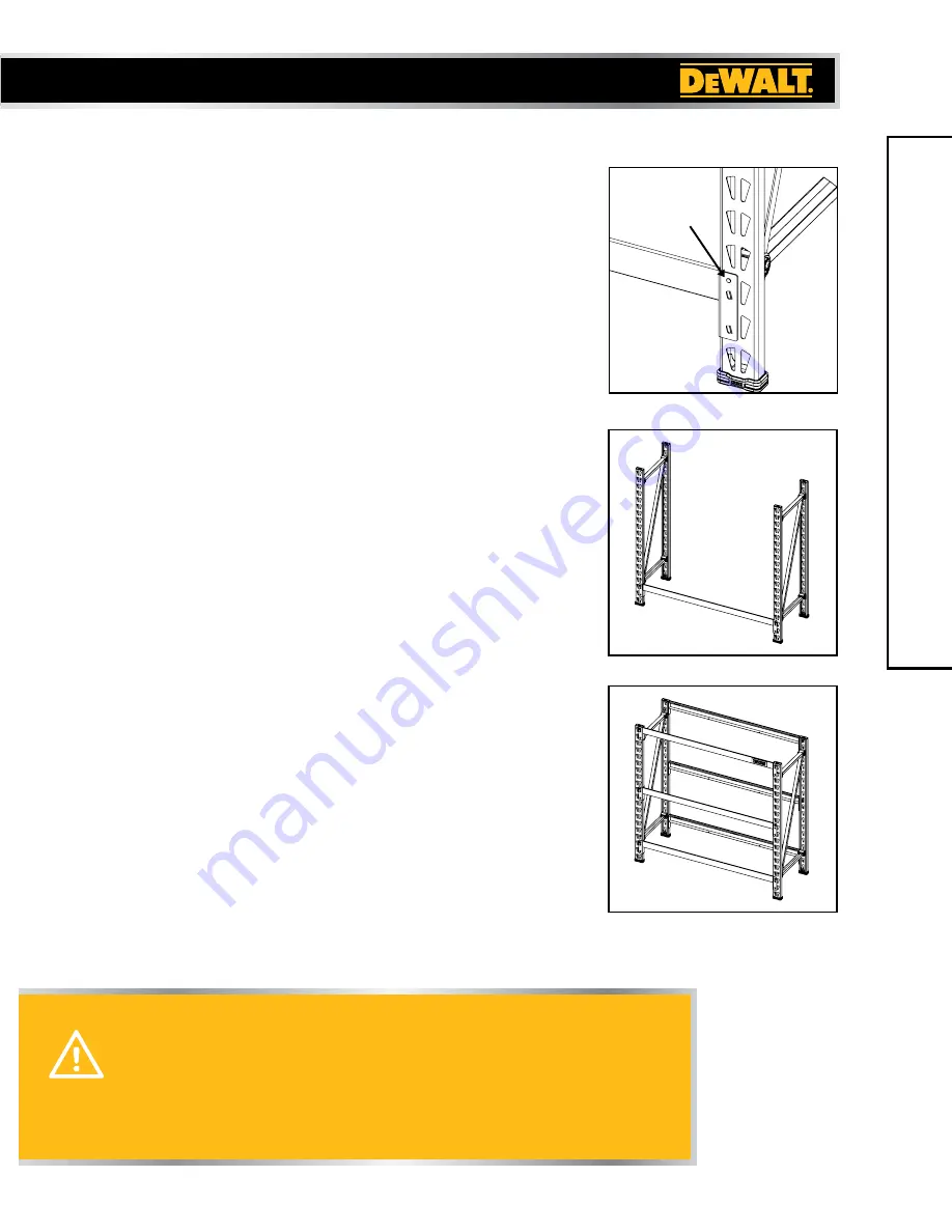
There is a set of locking tabs at both ends of every
crossbeam. To begin assembly, take one crossbeam and
insert the tabs into two of the holes on the lower portion of
one upright frame. Engage the locking tabs into the holes
using a downward motion. The locking pin hole should be at
the top. Make sure the end of the crossbeam is flush against
the upright frame.
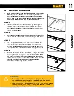
STEP 2
•
Repeat for the opposite side of the upright frame. Tap
the ends of the crossbeam closest to the upright frames
with a rubber mallet until fully seated. The crossbeam and
locking tabs should easily slip into place. If they do not, then
recheck the alignment of the teardrop-shaped holes and
tabs. Too much force may damage the interlock between the
crossbeam and upright frame.
STEP 3
•
Using the methods listed above, install another crossbeam
to the opposite side of the upright frames, parallel to the first
crossbeam you installed. Make sure both crossbeams are at
the same level.
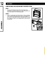
STEP 4
•
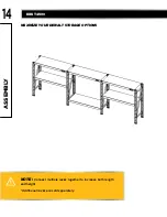
Continue by installing the middle and top sets of crossbeams
to the upright frames. Make sure the crossbeams are attached
at the same level on both sides. If you plan to stack another
DXST4500 Industrial Rack on top, then DO NOT attach the
third set of crossbeams to the very top of the upright frames.
See Page 13 for Complete Stacking Instructions.
A
SSEMBL
Y
LOCKING
PIN HOLE
FPO
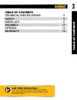
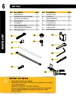
Summary of Contents for DXST4500
Page 2: ......


