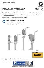
For portable dispensing of water-based and oil-based non-flammable materials.
Not approved for use in explosive atmospheres or hazardous (classified) locations.
For professional use only.
125 psi (0.86 MPa, 8.6 bar) Maximum Working Pressure
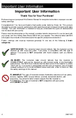
Important Safety Instructions
Read all warnings and instructions in this manual
before using the equipment. Be familiar with the
controls and the proper usage of the equipment.
Save these instructions.
3A8110C
EN
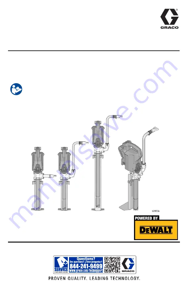
Operation, Parts
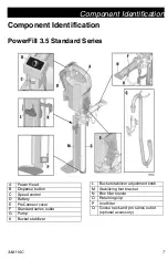
PowerFill™ 3.5 Standard Series,
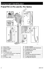
Pro Series, and XL Pro Series
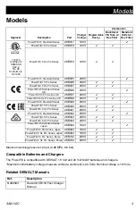
Use only genuine Graco replacement parts.
The use of non-Graco replacement parts may void warranty
.
Summary of Contents for Graco PowerFill 3.5 Standard 26B417
Page 39: ...Graco Information 3A8110C 39 ...


