10
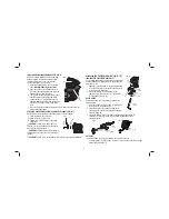
2. Adjust the length of the guide by pulling out or pushing inward to achieve the
desired length as shown in Figure 12.
3. Secure the guide in place by turning the depth/cut adjustment knob (P)
clockwise. To release the guide, turn the depth/cut adjustment knob
counterclockwise.
P
FIG. 11
FIG. 12
F
G
NOTE:
The guide arm can also be placed in the guard
assembly vertically in order to set the height of a cut.
Refer to Figure 13.
OPERATION
WARNING: To reduce the risk of serious personal
injury, turn the tool off and disconnect the battery
pack before making any adjustments or removing/
installing attachments or accessories.
An accidental
start-up can cause injury.
Installing and Removing the Battery Pack (Fig. 14)
NOTE:
For best results, make sure your battery pack is fully charged.
FIG. 14
I
H
FIG. 13
To install the battery pack (H) into the tool handle, align the battery pack with the
rails inside the tool’s handle and slide it into the handle until the battery pack is firmly
seated in the tool and ensure that it does not disengage.
To remove the battery pack from the tool, press the release button (I) and firmly pull
the battery pack out of the tool handle. Insert it into the charger as described in the
charger section of this manual.
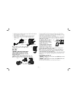
FUEL GAUGE BATTERY PACKS (FIG. 15)
T
FIG. 15
Some D
E
WALT battery packs include a
fuel gauge which consists of three green
LED lights that indicate the level of charge
remaining in the battery pack.
To actuate the fuel gauge, press and hold
the fuel gauge button (T). A combination
of the three green LED lights will illuminate
designating the level of charge left. When
the level of charge in the battery is below the usable limit, the fuel gauge will not
illuminate and the battery will need to be recharged.
NOTE:
The fuel gauge is only an indication of the charge left on the battery pack.
It does not indicate tool functionality and is subject to variation based on product
components, temperature and end-user application.
For more information regarding fuel gauge battery packs, please contact Stanley Black
& Decker, 82 Taryn Drive, Epping, VIC 3076 Australia or call 1800 338 002 or (NZ)
0800 339 258.
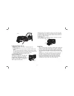
Proper Hand Position (Fig. 16)
WARNING:
To reduce the risk of serious personal injury,
ALWAYS
use proper hand
position as shown in Figure 16.
WARNING:
To reduce the risk of serious personal injury,
ALWAYS
hold securely in
anticipation of a sudden reaction.
Proper hand position requires the tool to be held as shown in Figure 16.
Summary of Contents for XR Li-Ion DCS355-XE
Page 1: ...DCS355 XE 18V BRUSHLESS CORDLESS MULTI TOOL INSTRUCTION MANUAL ...
Page 2: ......
Page 15: ......


