connectionS and PortS
23
DEWE3-A4L • Technical reference • Printing version 1.0.0 • September 22, 2022
Digital I/O connector specifications
Digit
al IN
Digital input
8 CMOS/TTL compatible digital inputs; weak pull-up via 100 kΩ
Overvoltage protection ±30 V
DC
, 50 V
PEAK
(100 ms)
Counter
4 counter channels; TTL input; shared with digital inputs
Counter modes
–
Waveform timing
–
Sensor modes
–
Event counting
Period, frequency, pulse width duty cycle and edge separation
Encoder (angle and linear)
Basic event count. gated count., up/down count. and encoder mode (X1, X2 and X4)
Counter resolution
32-bit
Counter time base
100 MHz
Time base accuracy
Typ. 2 ppm; max. 10 ppm
Max. input frequency
10 MHz
Sensor power supply
12 V (600 mA)
Digit
al OUT
Digital output
4 DO; TTL
Output indication
LED (green = high; off = low)
Maximum current
25 mA continuously
Power-on default
Low
Connector
D-SUB-25 socket
Tab. 7: Digital I/O connector specifications
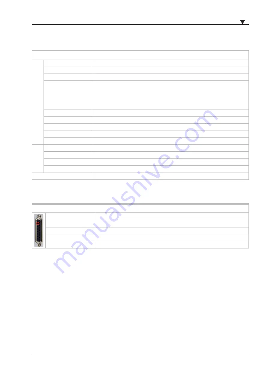
AUX terminal
AUX specifications
Functionality
Camera trigger, trigger output, acquisition clock and programmable clock output
Compatibility (output)
LVTTL, 10 mA
Overvoltage protection
±20 V
DC
Power-on default
Low
Connection
Pin 24 on digital I/O connector
Tab. 8: AUX specifications
The auxiliary terminal could be used as programmable frequency output for synchronizing external hardware.
The output can be set in the Sync Out AUX settings via
System Settings
→
Sync Setup
→
Sync Out Aux
:


