background image

Page 7

!

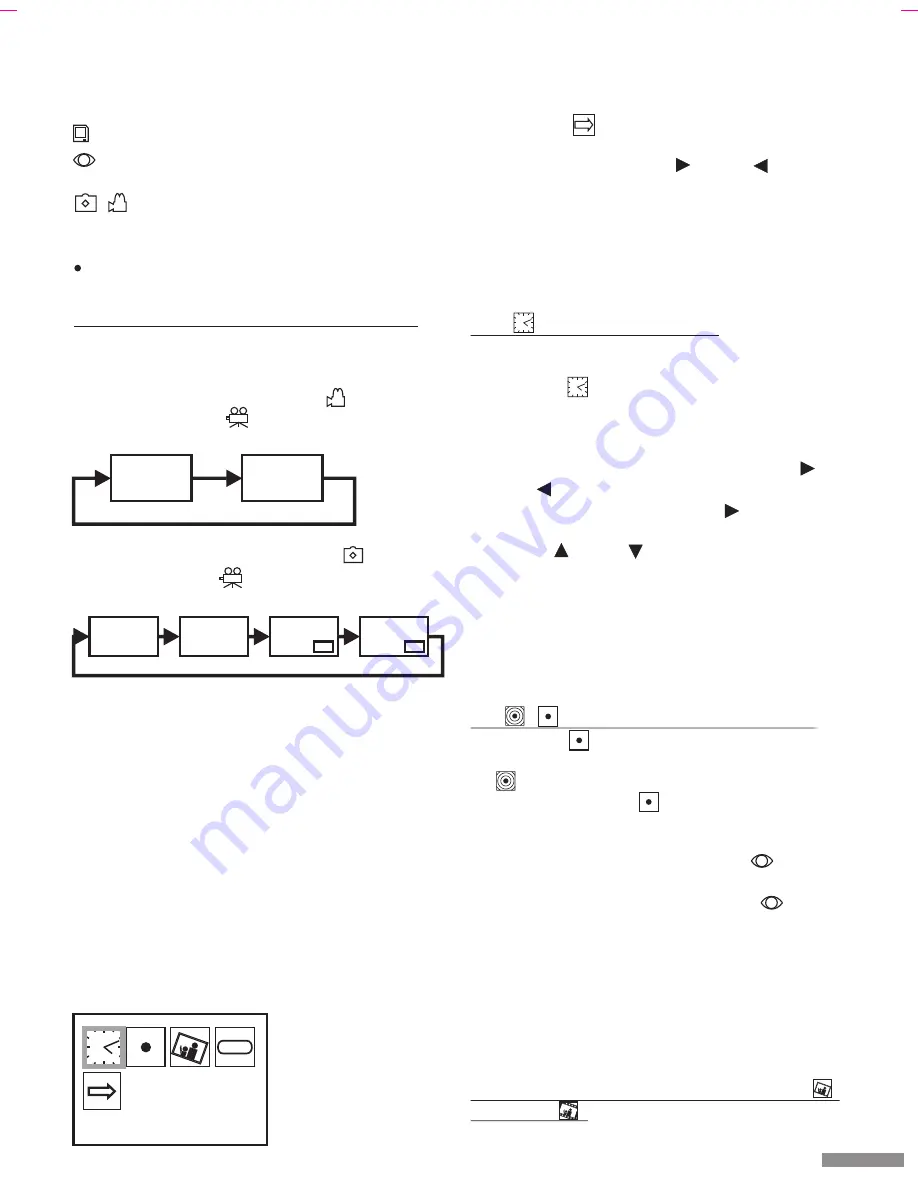
Press  the  “Menu”  button  [5]  to  access  the  setting 
mode. A screen with 5 icons is displayed (see Figure 
G): The top four icons symbolise the settings, and the 
bottom icon        is used to exit from the setting mode. 

The  blue  frame  shows  the  function  to  be  changed. You 
can move this with the buttons         [4] and          [2].
The framed setting can be selected by pressing the “OK” 
button [13].
You can leave the setting mode by pressing the “Menu” 
button [5].
If no button is pressed for 3 minutes in the setting mode, 
the setting mode is ended automatically.  

14.1          - Setting the date and time

The event recorder has an on-screen clock. The date and 
time from this are saved together with the stored images.

!

Select the          icon.

!

Press  the  “OK”  button  [13]  to  confirm  the  selection. 
The date (YYYY/MM/DD) is displayed at the bottom in 
the image. You can change the position which is red: 
Move the red position by pressing the buttons        [4] 
and                  [2].  You  reach  the  time  (HH:MM:SS)  by 
repeated  pressing  of  the  button              [4].  You  can 
change the value of the red position by pressing the 
buttons         [3] and        [12].

!

When  you  have  made  all  your  desired  changes, 
confirm  your  changes  by  pressing  the  “OK”  button 
[13].

Note:
The date and time settings are retained for up to 12 hours 
if the power supply is switched off.

14.2       /         - Switching recording mode ON/OFF

!

Select the            icon. 

!

Yo u   c a n   s w i t c h   t h e   r e c o r d i n g   m o d e   O N                      
       ("Motion Detection ON" is displayed at the bottom 
of the screen) or OFF       ("Motion Detection OFF" is 
displayed  at  the  bottom  of  the  screen)  by  repeated 
pressing of the “OK” button [13].

If recording mode is activated, the display         [9] lights 
in the live image mode.
If recording mode is switched off, the display        [9] does 
not light in the live image mode.

Tips: 
You can also select the corresponding setting in the live 
image mode directly by repeated pressing of the button 
[3].
The  recording  mode  cannot  be  switched  off  in  the  live 
image mode if recording is in progress.

14.3 Selection of the recording mode (still image      / 

video mode        )

Still  images  or  video  sequences  can  be  recorded 

screen.
The  status  of  the  event  recorder  is  represented  by  the 
following symbols:


Memory card is inserted


recording  mode  is  activated  (lights  green  for 

automatic recording in still image mode)

       /

Still  image  mode  /  video  mode  is  activated 

(lights red if the memory is full and the oldest 
images are being overwritten)


This  is  displayed  during  the  recording  of  a 

video sequence

13.1 Channel selection using the “Monitor” button

If  you  have  connected  an  optional  second  camera,  you 
can  toggle  between  video  input  CH1  and  CH2  by 
repeated pressing of the “Monitor” button [6].

#

If video mode is selected (symbol         is visible on 
the screen or LED             [8] lights), the channels will 
switch as follows:

#

If still image mode is selected (symbol       is visible on 
the screen or LED         [8] is not lit), the channels will 
switch as follows:

Notes:

#

The picture-in-picture display is used for an increased 
level of surveillance. As the smaller image has been 
digitalised,  the  resolution  is  low  and  the  reaction 
speed is slow.

#

The  picture-in-picture  display  is  only  possible  in  still 
image mode.

#

Only  the  camera  picture  which  is  displayed  in  full 
screen in live image mode can be stored.

#

After  the  video  recorder  has  been  switched  off  or  in 
the  event  of  power  failure,  the  camera  image  from 
channel 1 is displayed automatically even if channel 2 
had been selected previously.

14. Setting mode

GB / IE  -  7

      REC

CH1

CH2

CH2

CH1

CH2

CH1

CH2

CH1

Time Setup

EXIT

PAL

  Fig. G

EXIT

Summary of Contents for DV 622

Page 1: ...SECURITY CAMERA WITH DIGITAL IMAGE RECORDER SURVEILLANCE CAMERA WITH DIGITAL EVENT RECORDER DV 622 DV 622 Y KEYH A O HKEY H Operating and safety instructions page 2 12 GB IE K113b GR...

Page 2: ...g a plug in cable and a DSA 5P 05 FEU or DSA 5P 05 FUK power supply The camera is weatherproof protection class IP44 and is thus suitable for both the surveillance of indoor areas and also for install...

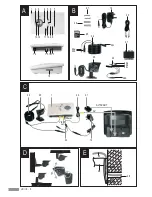
Page 3: ...GB IE 3 20 21 22 22a 22b 22c 22d 24c 24b 24a 23 25 27 26 19 24 1 2 3 4 5 6 7 8 9 10 11 12 13 14 17 18 16 15 A B C D 24 23 Power AV SCART AV Video out 1 20 21 22 19 E 28 30 29...

Page 4: ...t 24 Connection cable 25 SD memory card 26 Wall plugs 27 Screws 5 Technical data Event recorder DVS 100 Operating voltage 5 V DC Power consumption max 500 mA Video inputs 2 x Composite Signal 1 0 Vss...

Page 5: ...er remove the SD memory card from the device or switch the device off while recording Otherwise there is a risk of damage to the card and loss of the stored data 7 Location of the event recorder Obser...

Page 6: ...n activated factory setting The date and time are displayed on the top right of the Connect either the free plug of the video output cable to the AV cinch video input of a video monitor or television...

Page 7: ...d off the display 9 does not light in the live image mode Tips You can also select the corresponding setting in the live image mode directly by repeated pressing of the button 3 The recording mode can...

Page 8: ...ences Select the distance from the object according to the desired detail recognition Note that fast moving objects appear blurred for the digital storage automatically when movement is detected Selec...

Page 9: ...itor or to a TV using the cable 20 and the SCART adapter 21 if needed see Fig C If you press the Play button 10 repeatedly not possible if a recording is being made the following sequence is displayed...

Page 10: ...nce data individual directories or all data at the same time Deleting data on a PC is quicker and more flexible than on the event recorder 18 Manual recording Quick Shot This function enables the manu...

Page 11: ...cable connection between event recorder and TV is not correct The wrong channel on the TV has been selected The event recorder is switched off You have selected the wrong video input on the video reco...

Page 12: ...plan com 2 DV 622 C 80 DVS 100 DSA 5P 05FEU DSA 5P 05FUK IP44 SD 14 17 15 18 16 19 17 20 18 Quick Shot 20 19 20 20 21 21 21 22 21 23 21 24 22 1 12 2 12 3 13 4 13 5 13 6 14 7 14 8 14 9 15 10 15 11 15 1...

Page 13: ...ay 11 Quick Shot 12 Photo AVI AVI 13 OK 14 15 CH1 CH2 16 17 18 SD B 19 20 21 Scart 22 23 24 25 SD 26 27 5 DVS100 5V DC 500mA 2 Composite 1 0 Vss 10 75Ohm 1 Composite Pixel 640 x 480 320x240 AVI 1 5 AV...

Page 14: ...GR 14 3Lux LED 10 50 C x x 38 x 38 x 48 mm 5 7 g IP44 DSA 5P 05FEU DSA 5P 05FUK 100 240V 50 60Hz 0 2A 5V DC 1A II 6 5 V DC 230 V 50 Hz SD SD 7 8...

Page 15: ...GR 15 9 C 23 24c 24a CH1 15 24b 22a 22b 22c 19 22d 17 20 16 AV Cinch VIDEO Scart Scart Scart 10 360 D 30 28 10 mm E 29 27 26 27 mm 25 mm D 11 SD 25 SD 18 19 230VAC AV 14 7 12 12 1 12 2 12 3...

Page 16: ...REC GR 16 SD SD SD SD SD 640 x 480 JPG 1 320 x 240 AVI 5 10 SD 12 4 SD 13 13 1 Monitor CH1 CH2 Monitor 6 8 8 PIP PIP 1 2 2007 01 07 14 36 58 F CH1 CH2 CH2 CH1 CH2 CH1 CH2 CH1...

Page 17: ...SC 14 Menu 5 5 G 4 2 OK 13 5 3 14 1 OK 13 MM 4 2 4 3 12 OK 13 12 14 2 OK 13 Motion Detection ON Motion Detection OFF 9 9 3 14 3 OK 13 Capture Format Photo CaptureFormatAVI 8 8 12 Photo AVI 14 4 PAL 50...

Page 18: ...EXIT GR 18 14 5 OK 13 5 15 PIP Motion Detection 3 9 75 9 JPG 1 9 REC 10 5 AVI 1 5m Motion Detection 3 X 9 JPG AVI 12 1 CH1 EXIT...

Page 19: ...0 CH1 12 12 16 SD 16 1 14 SD 18 SD DCTV 08 01 09 00 9 2008 AVI JPG 22253400 JPG 22 25 MediaPlayer 16 2 20 Scart 21 C Play 10 16 2 1 Play 10 4 2 Dia Show 4 2 Dia Show H 3 16 2 2 6 Play 10 6 2007 01 09...

Page 20: ...00 07 01 12 01 3 12 OK 13 6 2 6 16 2 4 Play 10 NOFILE 17 17 1 11 4 2 YES OK 13 17 2 11 4 2 YES OK 13 17 3 Menu 5 4 2 YES OK 13 18 QuickShot Quick Shot 11 9 19 1 m 14 m 10 m 35m www dexaplan com SHOT...

Page 21: ...GR 21 20 21 22 3 23 Internet www dexaplan com e mail s e r v i c e d e x a p l a n d e 2107264057 8 30 17 00 DexaplanGmbH Paul B hringer Str 3 74229Oedheim 11 09 2008 11 09 2008 DV622 GBGR K113b GR...

Page 22: ...AV Monitor 1 SD CMOS 1 SD 12 SD GR 22 24...

Reviews: